
Method for enhanced gas monitoring in high particle density flow streams

a high particle density and flow stream technology, applied in the field of enhanced gas monitoring in high particle density flow stream, can solve the problems of gasification, high maintenance demand on the analysis system, incomplete combustion of process co in the exhaust, etc., to improve measurement accuracy and reliability, enhance the light transmission through a particle-laden medium, and improve the overall signal quality

Active Publication Date: 2005-09-13
LAIR LIQUIDE SA POUR LETUDE & LEXPLOITATION DES PROCEDES GEORGES CLAUDE
View PDF6 Cites 8 Cited by
  • Summary
  • Abstract
  • Description
  • Claims
  • Application Information

AI Technical Summary

Benefits of technology

The present invention provides a method for enhanced gas monitoring in high particle density flow streams. This method improves the overall signal quality, resulting in better measurements accuracy and reliability. It also reduces mechanical vibration and optical access issues, and facilitates optimal process control. The method allows for continuous, near real-time measurements of the species concentration in the waste gases, with acceptable accuracy. It can be used in industrial processes that experience high particle densities, temperature gradients, mechanical vibration, rapid variations in temperature and gas composition, and high radiation loads from the process itself. The method utilizes a more simply constructed, inexpensive and reliable sampling apparatus. Additionally, the method provides a durable method that does not require undue replacement of equipment and can be adapted for use in high temperature environments.

Problems solved by technology

For example, processes showing an excess of CO in the exhaust are exhibiting incomplete combustion and a potential loss of energy.
Many industrial processes, such as electric arc furnaces (EAF), waste incineration, and gasification, pose a special problem for off-gas composition due to the high gas temperature and the level of particles present.
Probe plugging and corrosion problems can place a high maintenance demand on an analysis system, making it unattractive for routine use.
In addition, extractive gas monitoring suffers slow response times that can be several tens of seconds to minutes to record the gas analysis result.
Slow response time becomes a significant factor on dynamic processes such as an EAF, where conditions can be changing at a rate faster the diagnostic response, resulting in delays for applying process control.
The combination of probe maintenance and slow response time issues make the technique unattractive on extremely harsh combustion systems.
These processes are particularly harsh, with exhaust gas temperatures less than about 1600 C and particle densities of 10 g / Nm3 to 100 g / Nm3.
Stantec and Air Liquide have demonstrated extractive sampling monitoring of the off-gas, but probe maintenance often limits the usefulness and duration of conducting continuous day-to-day monitoring of the processes.
However, working in the mid-IR range requires cryogenic cooling of the laser, and the system is not compatible with fiber optic components.
Therefore, conducting a path-averaged measurement at the gap position will lead to error, due to the uncertainty in the true path length of the measurement.
Additionally, the combination of the long pathlength through the duct (typically four to eight feet long) and particle densities results in severe laser beam attenuation.
The combination of these two effects can be detrimental to the measurement and place limitations on the accuracy of measured concentration values.
Despite the shortened path length, difficulties in obtaining adequate light transmission persisted due to the high particulate levels present.
Thus, a problem associated with methods for gas monitoring in high particle density flow streams is that they provide a slow response time and thereby do not adequately indicate process conditions to enable optimal process control.
Still another problem associated with methods for gas monitoring in high particle density flow streams that precede the present invention is that they do not facilitate optimal use of the potential energy present in the process by-products for heat generation.
Yet another problem associated with methods for gas monitoring in high particle density flow streams that precede the present invention is that they are susceptible to probe plugging and corrosion.
An even further problem associated with methods for gas monitoring in high particle density flow streams that precede the present invention is that they require undue replacement of the monitoring equipment.
Still a further problem associated with methods for gas monitoring in high particle density flow streams that precede the present invention is that they do not provide continuous, near real-time measurements of the species concentration in the waste gases, with acceptable accuracy, so as to facilitate an adapted dynamic monitoring of process characteristics.
Another problem associated with methods for gas monitoring in high particle density flow streams that precede the present invention is that they do not adequately facilitate control of the CO and H2 combustion by-products.
Yet another problem associated with methods for gas monitoring in high particle density flow streams is that they are not readily adaptable for use in industrial processes that experiences high particle densities, temperature gradients, mechanical vibration, rapid variations in temperature and gas composition, and high radiation loads from the process itself.
Another problem associated with methods for gas monitoring in high particle density flow streams is that they do not adequately provide continuous monitoring of the process conditions.
Still another problem associated with methods for gas monitoring in high particle density flow streams is that they cannot be adapted readily for use in high temperature environments and still provide a durable method that does not require unduly frequent replacement of equipment.

Method used


Image

  • Method for enhanced gas monitoring in high particle density flow streams
  • Method for enhanced gas monitoring in high particle density flow streams
  • Method for enhanced gas monitoring in high particle density flow streams

Examples


Embodiment Construction

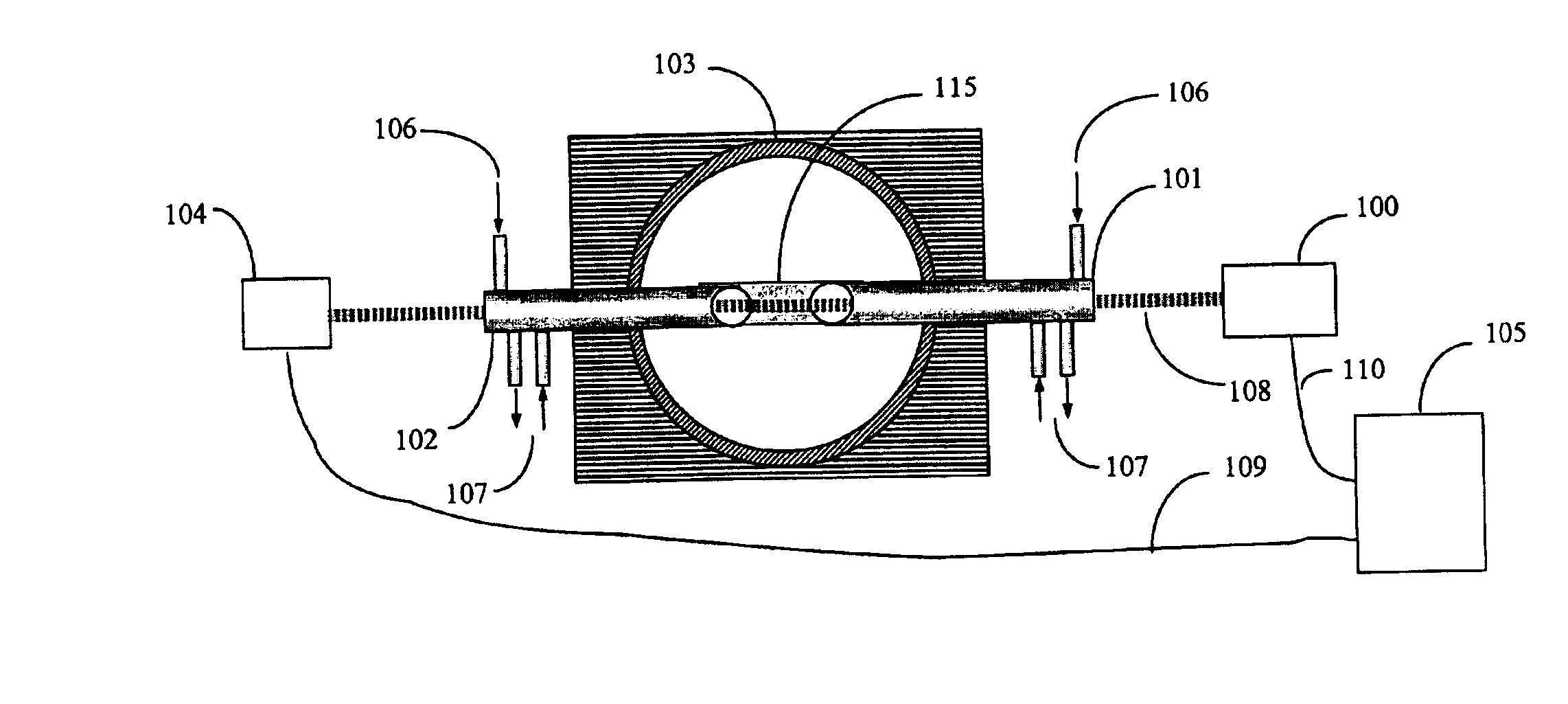
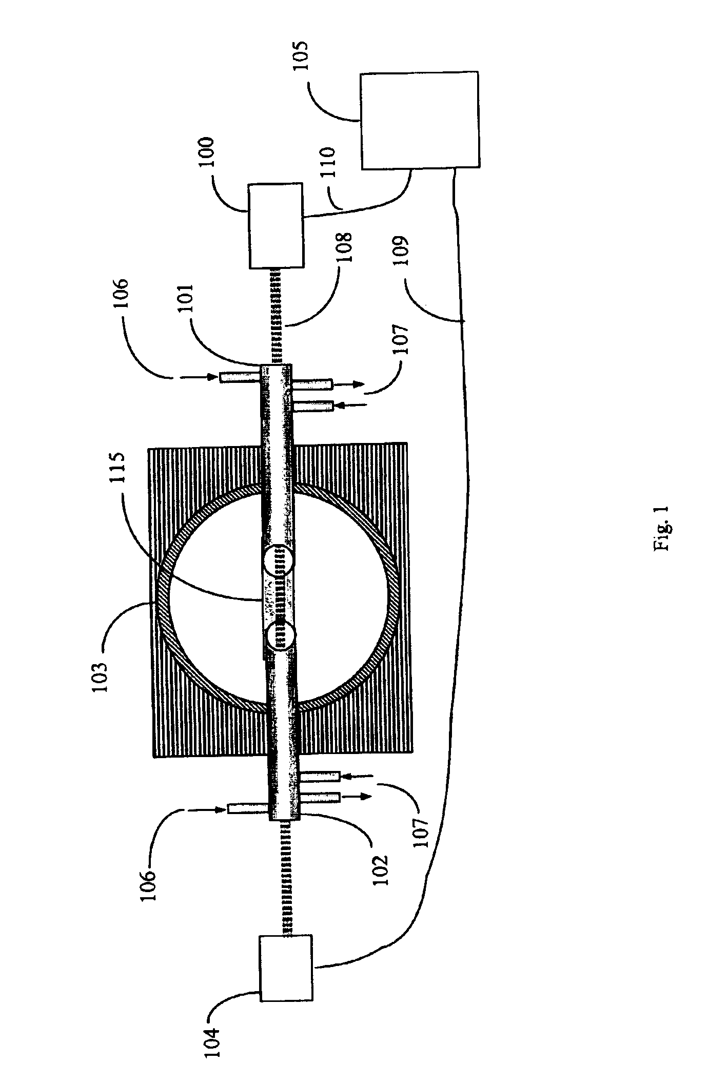
[0046]A method for conducting laser absorption measurements in high temperature process streams having high levels of particulate matter is disclosed. An impinger is positioned substantially parallel to a laser beam propagation path and at upstream position relative to the laser beam. Beam shielding pipes shield the beam from the surrounding environment. Measurement is conducted only in the gap between the two shielding pipes where the beam propagates through the process gas. The impinger facilitates reduced particle presence in the measurement beam, resulting in improved SNR (signal-to-noise) and improved sensitivity and dynamic range of the measurement. In a preferred embodiment, the method is adapted for use in an electric arc furnace (EAF).

[0047]To address reduce the effects of pathlength, particulate matter, and mechanical vibration from an industrial process exhaust stream, such as an EAF, a set of water-cooled pipes can be used to act as a shielding around the laser beam. A m...


PUM

PropertyMeasurementUnit
lengthsaaaaaaaaaa
diametersaaaaaaaaaa
sizeaaaaaaaaaa

Abstract

A method for conducting laser absorption measurements in high temperature process streams having high levels of particulate matter is disclosed. An impinger is positioned substantially parallel to a laser beam propagation path and at upstream position relative to the laser beam. Beam shielding pipes shield the beam from the surrounding environment. Measurement is conducted only in the gap between the two shielding pipes where the beam propagates through the process gas. The impinger facilitates reduced particle presence in the measurement beam, resulting in improved SNR (signal-to-noise) and improved sensitivity and dynamic range of the measurement.

Description

CROSS REFERENCE TO RELATED APPLICATION[0001]This application claims the benefit of U.S. Provisional Application No. 60 / 356,103, filed Feb. 11, 2002.BACKGROUND OF THE INVENTION[0002]1. Field of the Invention[0003]A method for conducting laser absorption measurements in high temperature process streams having high levels of particulate matter is disclosed. An impinger is positioned substantially parallel to a laser beam propagation path and at upstream position relative to the laser beam. Beam shielding pipes shield the beam from the surrounding environment. Measurement is conducted only in the gap between the two shielding pipes where the beam propagates through the process gas. The impinger facilitates reduced particle presence in the measurement beam, resulting in improved SNR (signal-to-noise) and improved sensitivity and dynamic range of the measurement.[0004]2. Description of Prior Art[0005]Monitoring the off-gas composition from combustion processes is useful for determining th...

Claims


Application Information

Patent Timeline
Patent Type & Authority Patents(United States)
IPC IPC(8): G01N21/85G01N21/03G01N21/09
CPCG01N21/8507G01N21/09
Inventor VON DRASEK, WILLIAM A.MULDERINK, KENNETH A.MARIN, OVIDIU
Owner LAIR LIQUIDE SA POUR LETUDE & LEXPLOITATION DES PROCEDES GEORGES CLAUDE
Learn More