Information reading and recording apparatus

a technology applied in the field of information reading and recording apparatus, can solve the problems of reducing the effective na, spherical aberration still present, and difficulty in cost reduction, and achieve the effects of generating small noise, reducing noise, and high performan

Inactive Publication Date: 2005-09-13
MINEBEA CO LTD
View PDF1 Cites 81 Cited by
  • Summary
  • Abstract
  • Description
  • Claims
  • Application Information

AI Technical Summary

Benefits of technology

[0030]The present invention has been made in light of the above, and it is an object of the present invention to provide a small, low-profile, simple and inexpensive information reading and recording apparatus by providing a super-resolution cut-off means havi

Problems solved by technology

However, the spherical aberration is still present after only limiting the aperture to decrease the effective NA.
In the second conventional example, in addition to the problem associated with the first conventional example, expensive integrated laser units are required, resulting in difficulty with cost reduction.
In the third conventional example, two laser diodes with different wavelengths are required, and the cost of th

Method used


Image

  • Information reading and recording apparatus
  • Information reading and recording apparatus
  • Information reading and recording apparatus

Examples


first embodiment

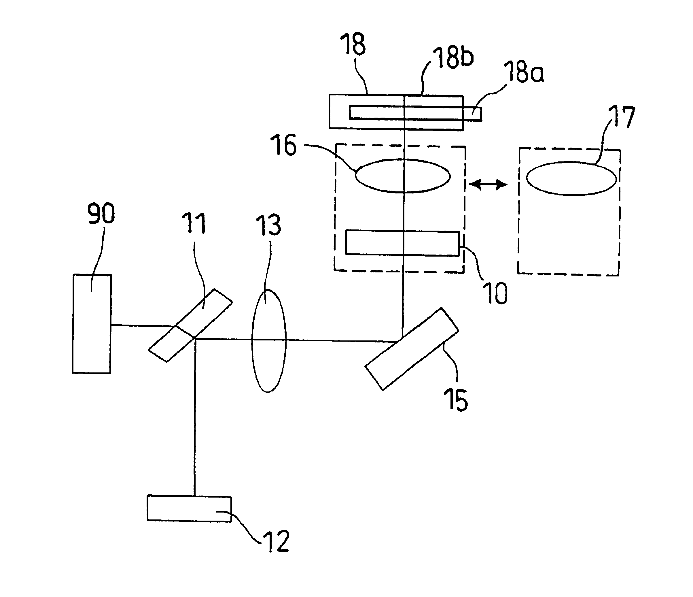
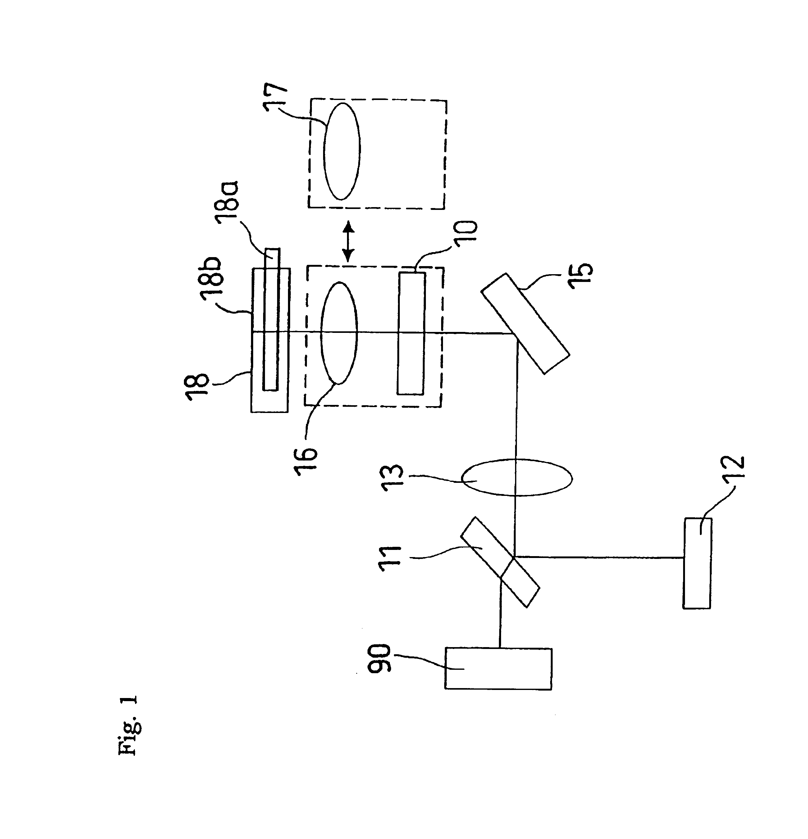
[0059]the present invention will be described with reference to FIG. 1. A laser diode 12 appropriate for CDs (wavelength: 780 nm) and a half mirror 11 which is a beam splitter element to guide a laser beam to a collimating lens 13 and to make a reflected laser beam from a disk 18 incident on a photo-detector 90 corresponding to the wavelength of the laser diode 12 for CDs are provided. The laser beam having passed through the collimating lens 13 is reflected by a reflecting mirror 15 toward an objective lens 16 or 17, and made incident on the disk 18. The reflecting mirror 15 is not an essential optical component, and an optical system can be constituted without using any reflecting minor. The disk 18 (DVD 18a or CD 18b) is put on a drive mechanism (not shown), and rotated thereby.

[0060]The objective lens 16 has a high numeral aperture (high NA) for DVDS, and the objective lens 17 has a low numeral aperture (low NA) for CDs. The aforementioned super-resolution cut-off filter 10 havi...

second embodiment

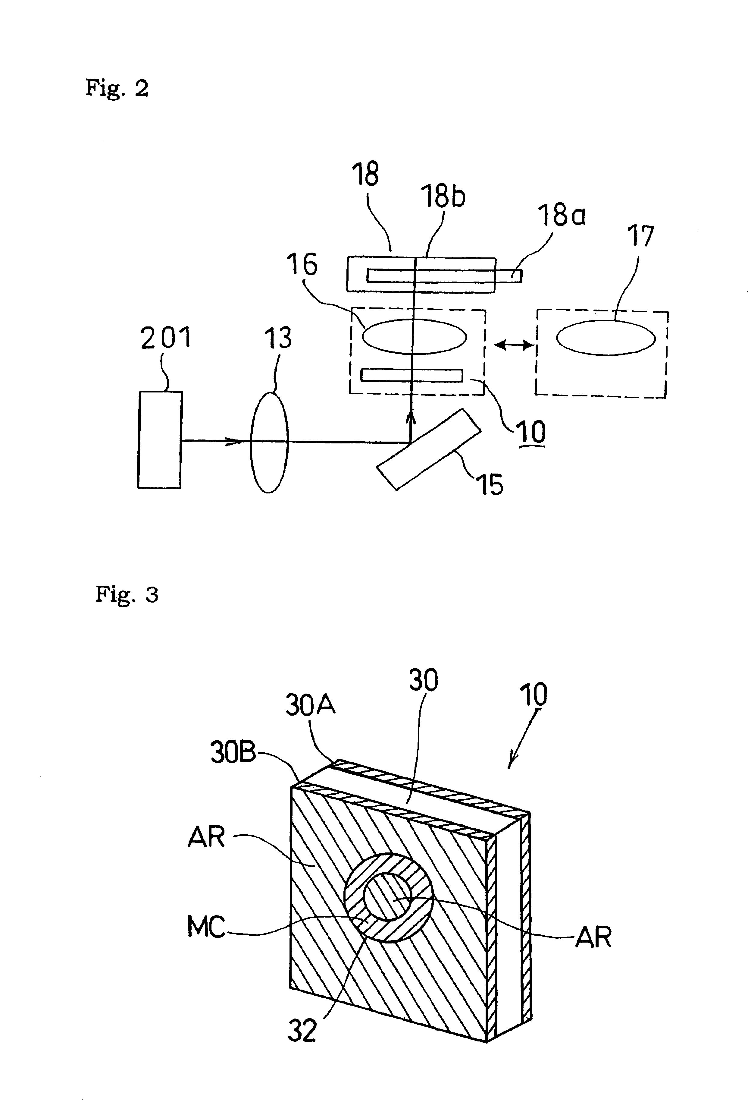
[0066]the present invention will be described with reference to FIG. 2. The information reading and recording apparatus comprises an integrated laser unit 201 having a semiconductor laser appropriate for CDs and a photodetector corresponding to the semiconductor laser packaged into an enclosure, a collimating lens 13 to collimate the laser beam, a reflecting mirror 15 to guide the laser beam having passed through the collimating lens 13 toward the disk 18, an objective lens 16 or 17, and a super-resolution cut-off filter 10 disposed immediately before the objective lens 16.

[0067]The integrated laser unit 201 has a laser beam source with a wavelength of 780 nm, which is appropriate to CDs, and which is integrated with the photo-detector. The objective lenses 16 and 17, and the super-resolution cut-off filter 10 in the second embodiment are structured and arranged in the same way as those in the first embodiment, and description thereof is omitted.

[0068]The information reading and rec...


PUM


Abstract

An information reading and recording apparatus includes a super-resolution cut-off filter having an annular metal reflection film at its center portion and disposed immediately before one of two objective lenses with a higher NA. When reading DVD, the one objective lens with a higher NA with the super-resolution cut-off filter disposed therebefore is positioned at the optical path. When reading CD, the other objective lens with a lower NA is positioned at the optical path. The laser beam reflected by a disk follows backward the incoming optical path to pass through a half mirror, and is received by a photo-detector to be converted into an electrical signal.

Description

BACKGROUND OF THE INVENTION[0001]1. Field of the Invention[0002]The present invention relates to an information reading and recording apparatus for recording media, such as an optical disk.[0003]2. Description of the Related Art[0004]In the current information input / output apparatus using light, such as CD (compact disk) drive, light emitted from a laser beam source is converged as a micro spot constituting a recording pit on a track provided on a disk-like recording medium such as a CD, presence or absence of the pit is recorded as information, and the presence or absence of the pit on the track is detected by means of reflected light from the track thereby reading the information.[0005]Recently, DVDs, which have a recording capacity about 7 times as large as that of CDs, are becoming remarkably popular along with the demand for an increased recording capacity. Increase in recording capacity means improvement of the recording density, which depends on the number of recording pits f...

Claims


Application Information

Patent Timeline
IPC IPC(8): G11B7/125G11B7/135G11B7/00G11B7/1365G11B7/1372G11B7/1381
CPCG11B7/1365G11B7/1381G11B2007/0006G11B2007/13727
Inventor NAKAMURA, MIZUKIKITAMURA, ATSUSHIMATSUMOTO, KOZO
Owner MINEBEA CO LTD
Why Eureka
Try Eureka