Roof bit and insert assembly

a technology for inserting and roofs, which is applied in the field of roof insert assembly, can solve the problems of excessive heat at the tip end of the roof, additional assembly time during original manufacturing, and high cost of replacing the entire center vacuum rotary drill bit, so as to reduce the displacement of the insert, accurate alignment, and high quality

Inactive Publication Date: 2005-09-20
KENNAMETAL INC
View PDF20 Cites 23 Cited by
  • Summary
  • Abstract
  • Description
  • Claims
  • Application Information

AI Technical Summary

Benefits of technology

[0010]In one embodiment, generally vertical sidewall surfaces of a depression keyway and vertical sidewall surfaces of a projection key provide mechanical resistance against lateral movement of the cutting insert. This mechanical resistance reduces displacement of the insert with respect to the bit body during brazing and thus a high quality, accurately aligned drill bit assembly is provided by applicants' invention. Additionally, it is believed that during drilling operations the vertical surfaces assist in resisting lateral displacement caused by lateral force loads and torques applied to the cutting ends of the insert.
[0011]The depression keyway is designed so as to minimize the effect of the axial load on the insert by avoiding sharp corners which tend to amplify nominal stress and provides for an insert of a proper carbide density after pressing.
[0012]Integral bit body protuberance means contact the insert along the slot, the protuberance means are cylindrical ridges, semispherical, circular, prisms, angular or an equivalent shape or form. The protuberance means adequately separate the insert within the slot and permit braze flow between the insert and slot. The protuberance means enhance braze flow when braze is fed between the insert body and bit body.
[0013]The overall bottom surface area of the cemented tungsten carbide insert is significantly increased by the keyway depression. The key and keyway increase the surface contact area between the bottom surface area of the insert and cooperating bottom surface of the slot. The increased surface contact area allows for additional braze to be applied between the insert and bit body slot enhancing the strength of the bond between the insert and bit body.
[0014]Another added benefit of the depression keyway is that the depression keyway in the tungsten carbide reduces the amount of tungsten carbide or other material needed to manufacture the insert. In comparison to an insert bit dimensionally equivalent in shape and size to applicants' insert without a keyway, 30%-50% by weight less tungsten is needed to make applicant's insert bit. Cemented tungsten carbide is relatively expensive and applicants, insert design significantly reduces material costs.
[0015]The invention requires a minimum number parts for assembly, reduces material cost and provides for a strong and precisely assembled roof bit.

Problems solved by technology

These conditions also generate excessive heat at the tip end of the roof bit assembly.
The hard wear resistant insert secured within the top working surface of the rotary drill bit body typically wears or dulls before the drill bit body becomes worn and unusable such that the user of the center vacuum rotary drill bit must either replace the entire rotary drill bit, attempt to replace the insert with a new insert of similar size, or attempt to resharpen the insert.
Replacement of the entire center vacuum rotary drill bit is costly and resharpening of the insert may only be performed a limited number of times before the top working surface of the drill bit body frictionally engages the material to be cut.
The support bar in these roof bits results in additional assembly time during original manufacturing or when replacing inserts onto a bit body.
The assembly of these roof bits can be even more time consuming and cumbersome in the field.
The support bar also requires maintaining additional parts and undesirable expanding inventories.

Method used


Image

  • Roof bit and insert assembly
  • Roof bit and insert assembly
  • Roof bit and insert assembly

Examples


Embodiment Construction

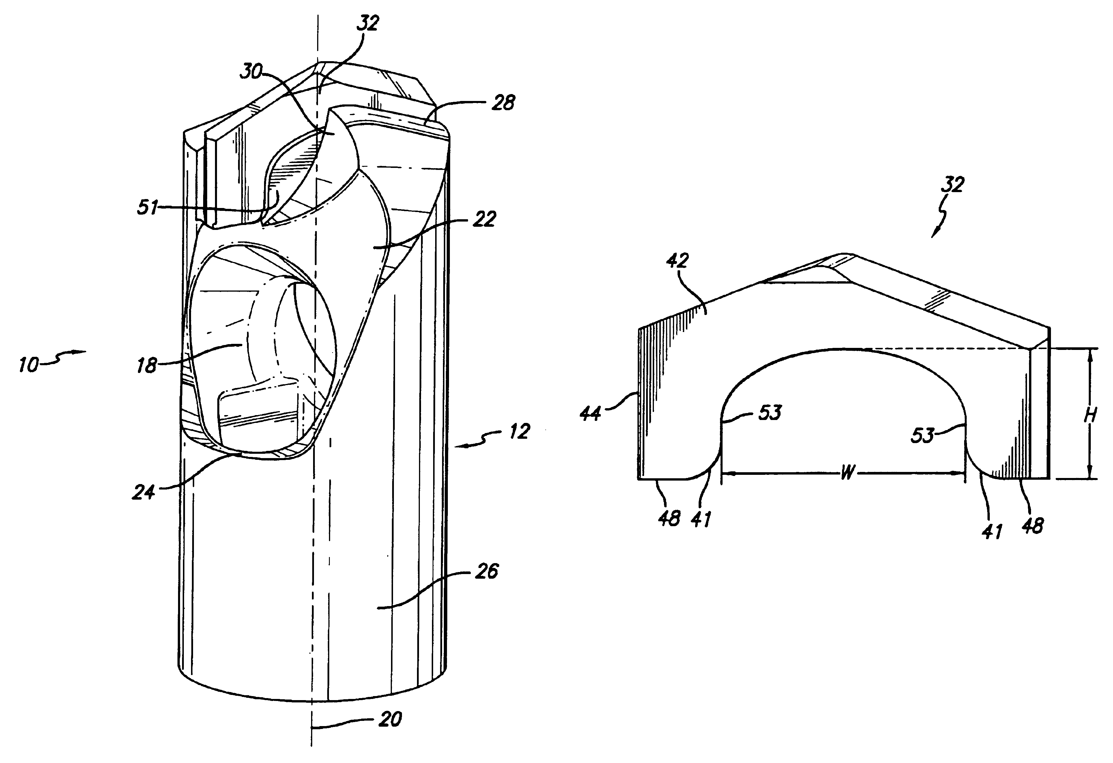
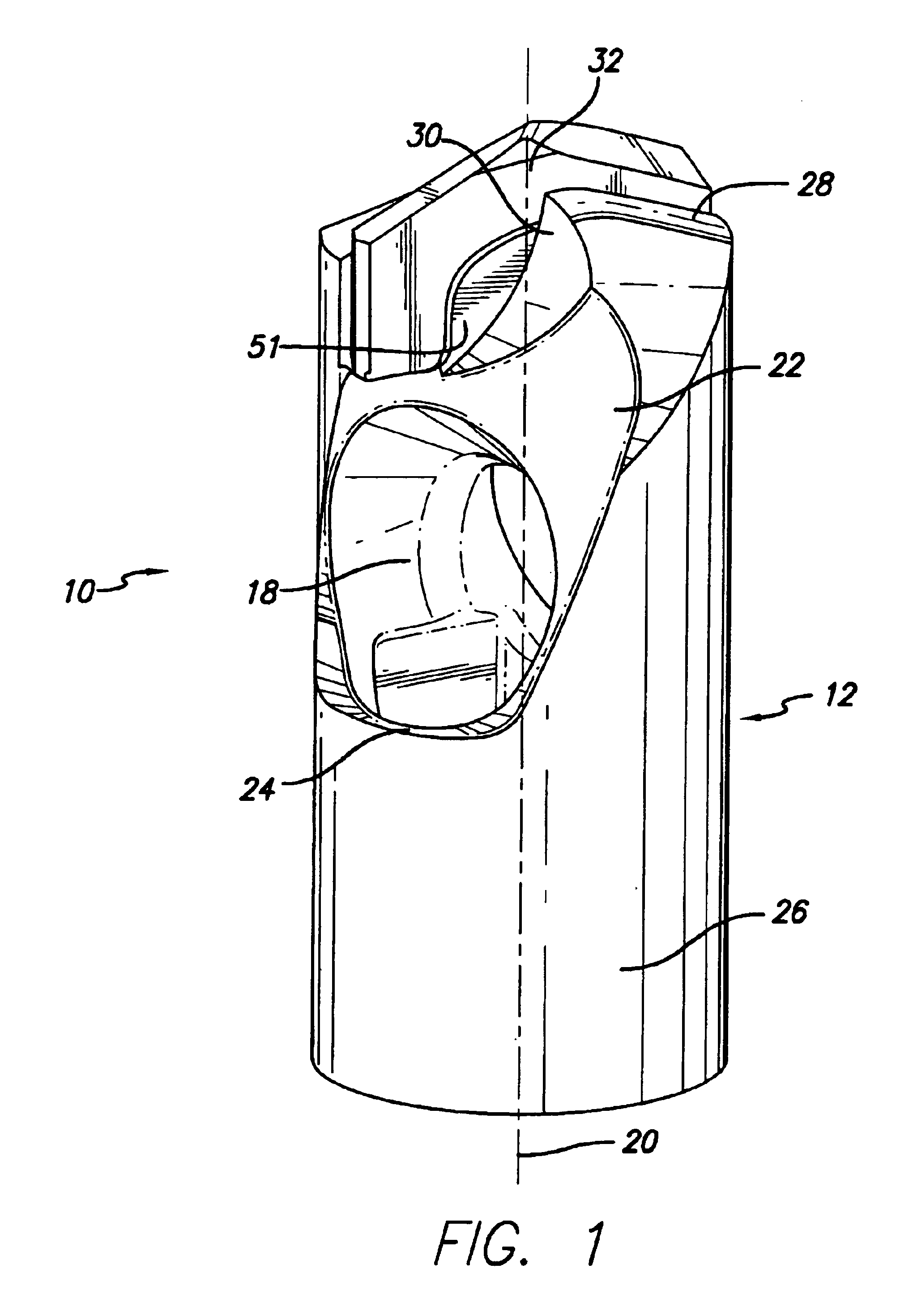
[0024]In the following description, like reference characters designate like or corresponding parts. Referring now to FIG. 1, there is shown a center vacuum rotary drill bit assembly 10 including an elongated cylindrical bit body 12 having a generally cylindrical section 26 and a top working surface 14.

[0025]The bit body 12 includes at least a pair of opposing dust collection openings 18 angularly positioned with respect to a central vertical axis 20 of the drill bit body. The dust collection openings 18 are disposed within recessed surfaces 22. As shown in FIG. 1, the openings 18 and recessed surfaces 22 cooperatively provide a pair of oppositely disposed, generally transverse, arcuate shaped shoulder portions 24.

[0026]The top working surface 14 of the drill bit body 12 has an irregular surface configuration defined by an alternating first pair of oppositely disposed trailing surfaces 28 and a second pair of oppositely disposed tapered compression surfaces 30. The trailing surfaces...


PUM


Abstract

A center vacuum rotary drill bit including a rotary drill bit body and an insert. The bottom surface of the slot has a projecting key that cooperates with a depression keyway of the insert. Generally vertical sidewall surfaces of a depression keyway and vertical surfaces of a projection key provide mechanical resistance against lateral movement of the cutting insert. This mechanical resistance reduces displacement of the insert with respect to the bit body during brazing and thus a high quality, accurately aligned drill bit assembly is provided by applicants' invention. The depression keyway is designed so as to minimize the effect of the axial load on the insert by avoiding sharp corners which tend to amplify nominal stress and provides an insert of a proper carbide density after pressing. Integral bit body protuberance means adequately separate the insert within the slot and permit braze flow between the insert and slot. The protuberance means enhance braze flow when braze is fed between the insert body and bit body.

Description

[0001]This application is a division of U.S. application Ser. No. 09 / 888,770, filed Jun. 25, 2001 now U.S. Pat. No. 6,684,968.RELATED APPLICATIONS[0002]This application is related to copending U.S. patent application Ser. No. 09 / 376,725, filed Aug. 17, 1999, to Ted R. Massa et al. (Case No. K-1313D), entitled “ROTATABLE CUTTING BIT ASEMBLY WITH WEDGE LOCK RETENTION ASSEMBLY.”FIELD OF THE INVENTION[0003]This invention relates to a roof bit assembly. More particularly, this invention relates to a roof bit insert assembly for securely connecting an insert onto a bit body.BACKGROUND OF THE INVENTION[0004]Roof bits are used in a violent environment in which heavy loads and torques are continually applied to the roof bits at a high rate. One inch diameter roof bits are commonly operated at about 250-600 rpm and 1000-8000 pounds thrust. These conditions also generate excessive heat at the tip end of the roof bit assembly.[0005]A hard wear resistant insert for use in a center vacuum rotary ...

Claims


Application Information

Patent Timeline
Patent Type & Authority Patents(United States)
IPC IPC(8): B23B51/00
CPCB23B51/00E21B10/58E21B10/60E21B21/16
Inventor BISE, DOUGLAS E.HAGA, PHILLIP W.MASSA, TED R.
Owner KENNAMETAL INC
Why Eureka
Try Eureka