Power distribution panel switch gear and a monitoring and control system having a distribution panel switch gear

a technology of distribution panel and switch gear, which is applied in the direction of instruments, nuclear elements, digital computer details, etc., can solve the problems of increasing the size of the apparatus, increasing the installation cost of each component of the apparatus, and increasing the dimensions of the apparatus, so as to simplify the configuration of the apparatus

Inactive Publication Date: 2005-09-20
HITACHI LTD
View PDF11 Cites 11 Cited by
  • Summary
  • Abstract
  • Description
  • Claims
  • Application Information

AI Technical Summary

Benefits of technology

[0008]An increase in the scale of the apparatus also poses the problems that the installation costs relating to each component of the apparatus correspondingly increase and hereby that the installation of the apparatus and the test processes thereof require longer periods of time.
[0009]In other words, since controllers are concentratedly installed in the central control room, process cables need to be laid over a long distance from the process devices to the central control room, this arrangement increases installation costs, coupled with increases in the number of input and output ports due to the scaling-up of the plant and the sophistication of the control system.
[0010]As the dimensions of the controllers increase with the sophistication of the control technology and function, the dimensions of the control equipment room also increase and this, in turn, increases installation costs.
[0017]An object of the present invention is to provide a power distribution panel switch gear, and a monitoring and control system, that can be simplified in terms of configuration.
[0025]According to the above-described means, since the protection and interlocking of a plurality of devices to be operated can be controlled using a single power distribution panel switch gear, the configuration of the apparatus can be simplified.
[0026]Also, since the operating and monitoring command output means and the monitoring information creating means are connected using wireless communication as a communication means for information exchange between both means and the monitoring information creating means also uses wireless communication as an input means for input of information relating to the plant, when the protection and interlocking of the plurality of devices to be operated are controlled in accordance with the commands output from the operating and monitoring command output means, the operating and monitoring command output means can directly acquire the plant information input from the monitoring information creating means, and even in the case that some of the functions of the monitoring information creating means are not working, the operating and monitoring command output means can directly acquire the plant information input from the monitoring information creating means and undertake the non-working functions of the monitoring information creating means by using acquired information, with the result that the protection and interlocking of a plurality of devices to be operated can be safely controlled.

Problems solved by technology

In the case of the related art described above, since each relay within the auxiliary-device interlocking relay panel and each switch of the power distribution panel switch gear are connected via independent cables and since the starting and stopping command signals relating to pump fans, the opening and closing command signals relating to motorized valves, and other command signals are also transmitted via cables, there are the problems that it is necessary to lay cables as many as there actually are the number of starting commands issued to the process relays functioning as the devices to be operated, and thus that the apparatus increases in dimensions.
An increase in the scale of the apparatus also poses the problems that the installation costs relating to each component of the apparatus correspondingly increase and hereby that the installation of the apparatus and the test processes thereof require longer periods of time.
In other words, since controllers are concentratedly installed in the central control room, process cables need to be laid over a long distance from the process devices to the central control room, this arrangement increases installation costs, coupled with increases in the number of input and output ports due to the scaling-up of the plant and the sophistication of the control system.
As the dimensions of the controllers increase with the sophistication of the control technology and function, the dimensions of the control equipment room also increase and this, in turn, increases installation costs.

Method used


Image

  • Power distribution panel switch gear and a monitoring and control system having a distribution panel switch gear
  • Power distribution panel switch gear and a monitoring and control system having a distribution panel switch gear
  • Power distribution panel switch gear and a monitoring and control system having a distribution panel switch gear

Examples


first embodiment

[0037]the present invention is described below using drawings.

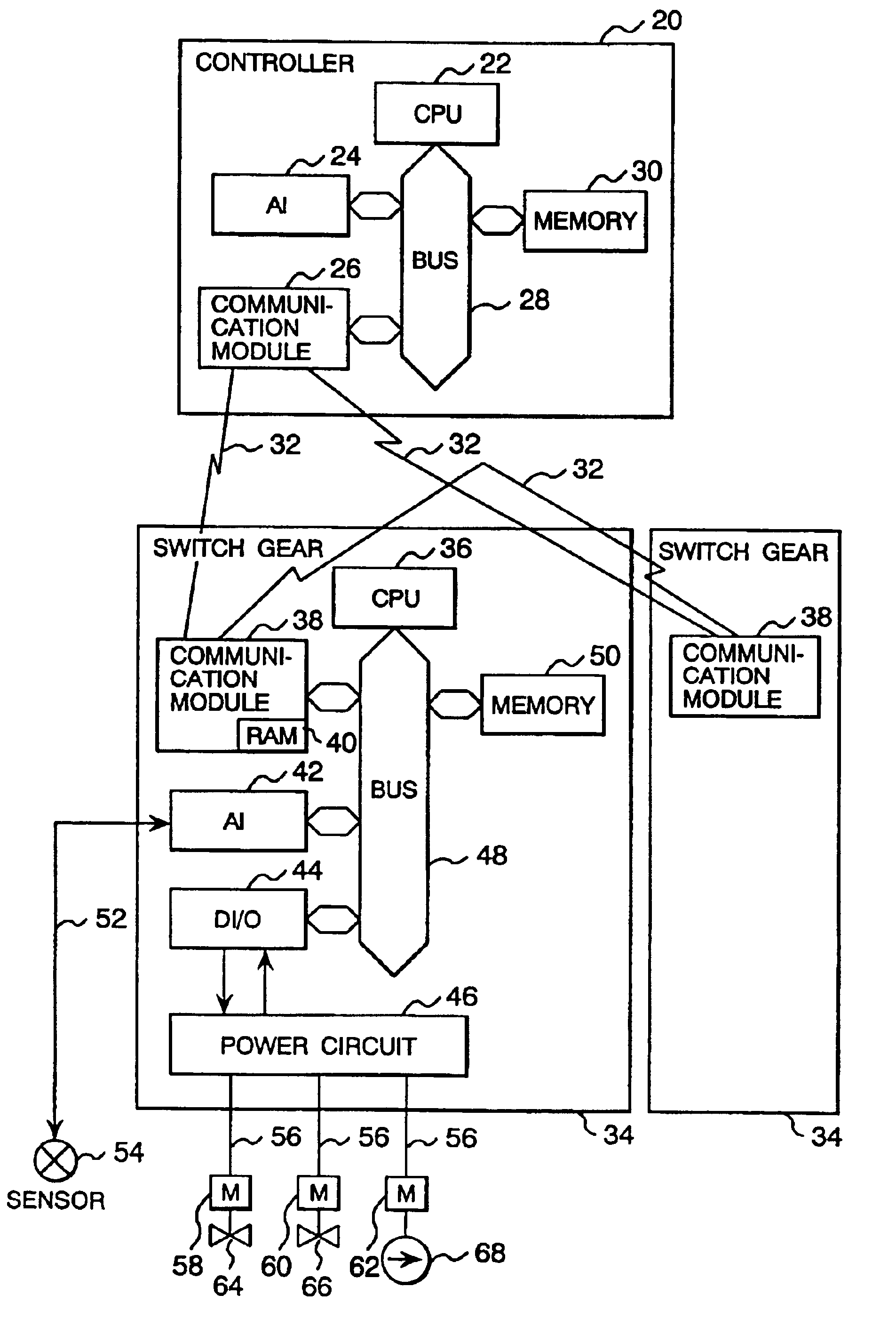
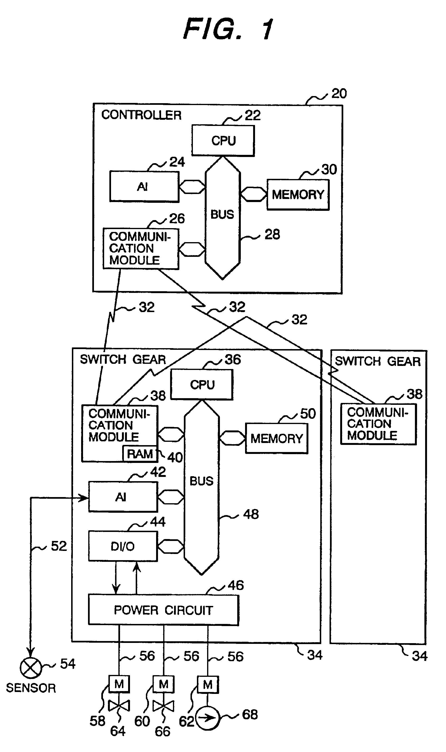
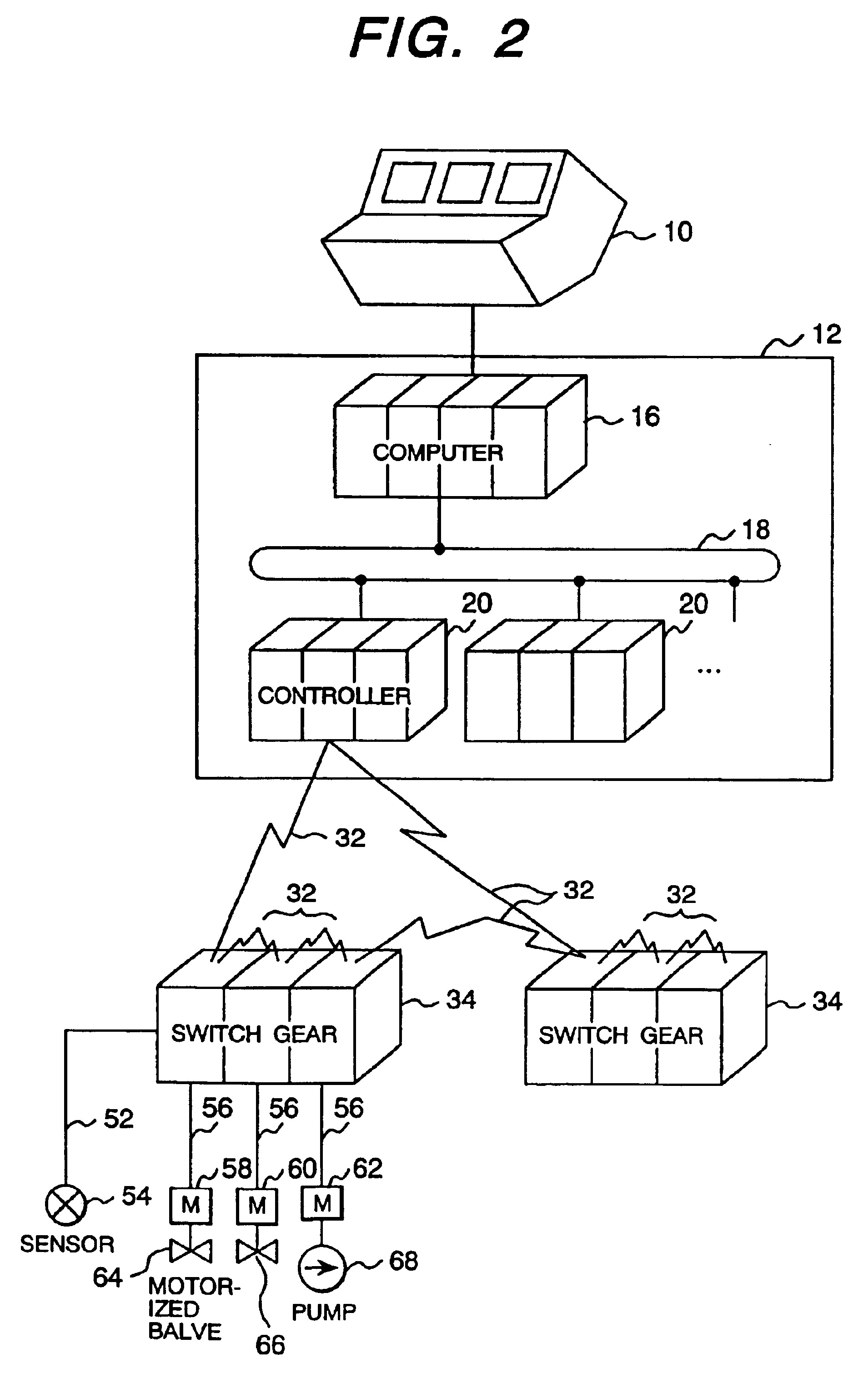
[0038]FIG. 1 is a configuration diagram showing the major blocks of an monitoring and control system which embodies the present invention applied to a thermal power plant. FIG. 2 is a total configuration diagram of the monitoring and control system.

[0039]In FIGS. 1 and 2, a computer 16, a network 18, and a plurality of controllers 20 are installed in a central controller room 12, wherein the computer 16 is connected to each of the controllers 20 via the network 18 and also connected to a main control panel 10. The main control panel 10 receives the monitoring / operation-associated commands of an operator and transfers the thus-received commands to the computer 16. The computer 16 creates various monitoring / operation-associated control commands from the received commands and then transfers the thus-created control commands to each controller 20 via the network 18.

[0040]Each controller 20 has a plurality of operating and mon...


PUM


Abstract

A monitoring and control system is provided having a control device, arranged in a central controller room, which provides commands to power distribution panel switch gear located in the field. The switch gear transmits and receives controlling and monitoring signals through wireless communication applying an evanescent mode. The switch gear has a power circuit connected to a plurality of devices to be operated. The switch gear is a panel comprising metal and non-metal surfaces, so that a portion of wireless waves in the evanescent mode travel out of the panel. A receiver is provided for monitoring the wireless waves that travel out of the panel. The wireless signals are compared with information stored in a diagnostics database, and are diagnostically evaluated to determine whether the signals are within a known normal operating range.

Description

[0001]The present application is a divisional of application Ser. No. 10 / 444,955, filed May 27, 2003, now abandoned the entire disclosure of which is incorporated herein by reference.BACKGROUND OF THE INVENTION[0002]1. Field of the Invention[0003]The present invention relates to a power distribution panel switch gear, a monitoring and control system, and an equipment diagnostic system relating to the same.[0004]2. Prior Art[0005]In a conventional atomic power plant, a system for operating various types of process devices, subject to commands from the main control panel, is constructed. For example, as described in the article “Instrumentation and Control, Automated IV, and the Control and Automation of Power Plants” disclosed in the July number of “Thermal and Atomic Power Generation-1993”, there are power plants equipped with a main control panel and a unit computer arranged in the central control room of the power plant, with an auxiliary-device sequence controller connected to th...

Claims


Application Information

Patent Timeline
Patent Type & Authority Patents(United States)
IPC IPC(8): H02J13/00G05B23/02
CPCH02J13/001H02J13/0075Y04S10/40Y04S40/126Y02E60/7853H02J13/00001H02J13/00026H02J13/00034Y02E60/00
Inventor SUGIHARA, MASASHIFUKAI, MASAYUKIITO, AKIOSHIMIZU, KATSUHITOKUSAKA, SATOSHINAMBA, SHIGEAKIKIMURA, TORU
Owner HITACHI LTD
Why Eureka
Try Eureka