Beam source

a beam source and beam technology, applied in the field of beam sources, can solve the problems that the above-described beam sources have not always been sufficient for forming high-density plasma, and achieve the effect of reducing the amount of charge buildup

Inactive Publication Date: 2005-09-27
EBARA CORP
View PDF15 Cites 20 Cited by
  • Summary
  • Abstract
  • Description
  • Claims
  • Application Information

AI Technical Summary

Benefits of technology

[0011]Setting the two upstream electrodes at the same potential stabilizes the potential of plasma formed therebetween, enabling the potential to be controlled as desired. Further, since the potential of the downstream electrode is the same as that of the chamber into which plasma is discharged, it is possible to emit ions accelerated between the two downstream electrodes as an energy beam, such as an ion beam or a neutral particle beam, into the chamber.
[0012]Further, the mesh electrode is formed of a conductive material in a thin plate shape and has a plurality of openings. The open area ratio of the electrode should be 85% or less. Accordingly, a charged particle beam can be easily formed from the high-density plasma between the two downstream electrodes with a relatively short sheath length.
[0013]Further, the two electrodes on the downstream end are separated by a distance of 5 millimeters or greater, and preferably by a distance of 10–30 millimeters. Accordingly, a relatively low-energy beam appropriate for micro-fabrication can be efficiently extracted from the high-density plasma.
[0014]Further, each of the beam-emitting holes formed in the beam-emitting electrode on the downstream end has a length-to-diameter ratio of 2 or greater. Accordingly, the accelerated beam between the two downstream electrodes can be emitted without loss of directivity or density.
[0015]Further, the voltage-applying means applies a positive-negative pulse-type voltage that alternately irradiates either positive ions and negative ions or positive ions and electrons. Accordingly, by alternately irradiating positive ions and negative ions (or electrons), high-precision etching and deposition processes can be conducted while reducing the amount of charge buildup on the surfaces of insulating materials, such as glass and ceramic materials.

Problems solved by technology

However, the above-described beam sources have not always been sufficient for forming high-density plasma and for efficiently extracting from this plasma an energy beam, such as an ion beam or neutral particle beam, having high directivity and high density.

Method used


Image

  • Beam source
  • Beam source
  • Beam source

Examples


Embodiment Construction

[0025]A beam source according to preferred embodiments of the present invention will be described while referring to the accompanying drawings.

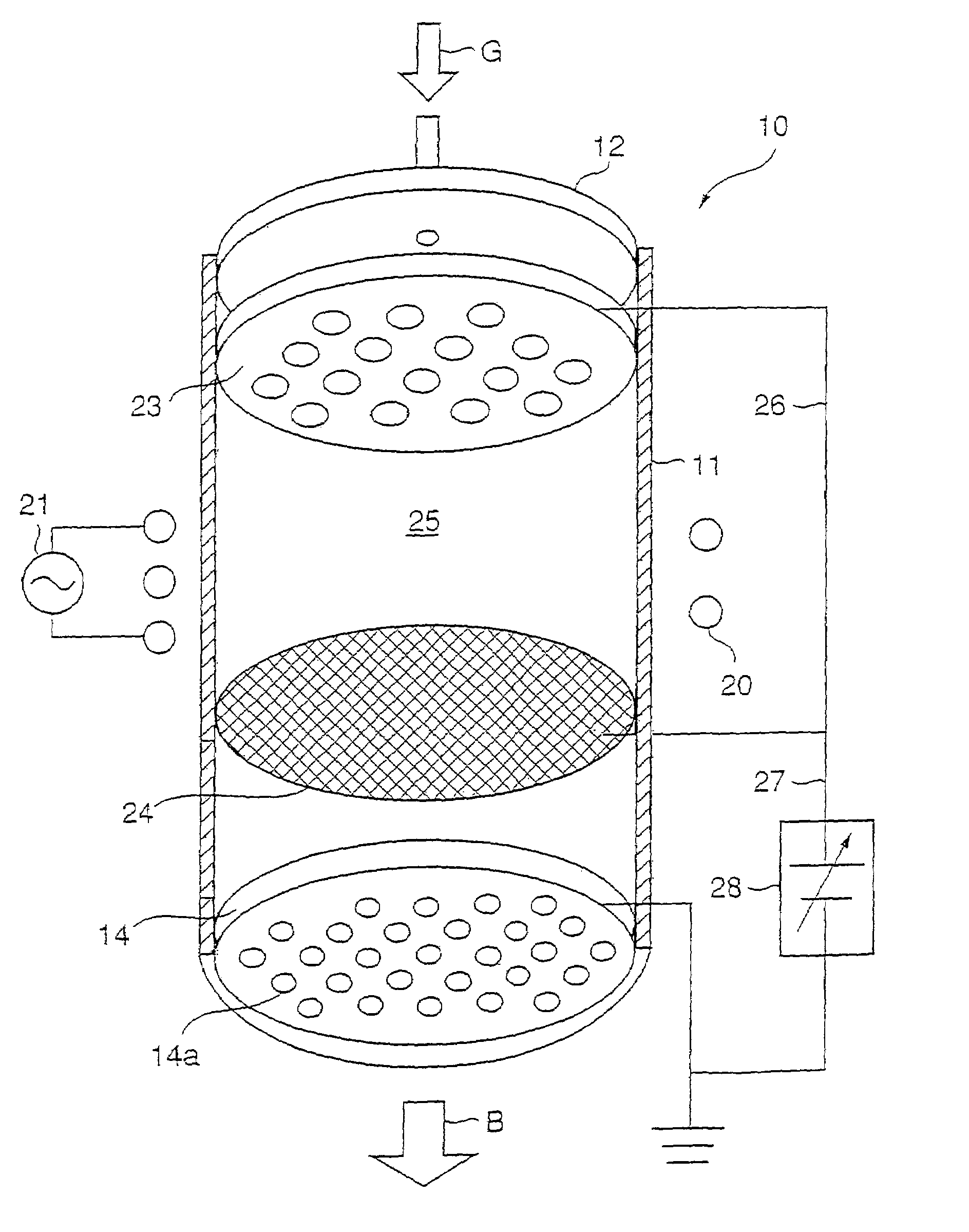
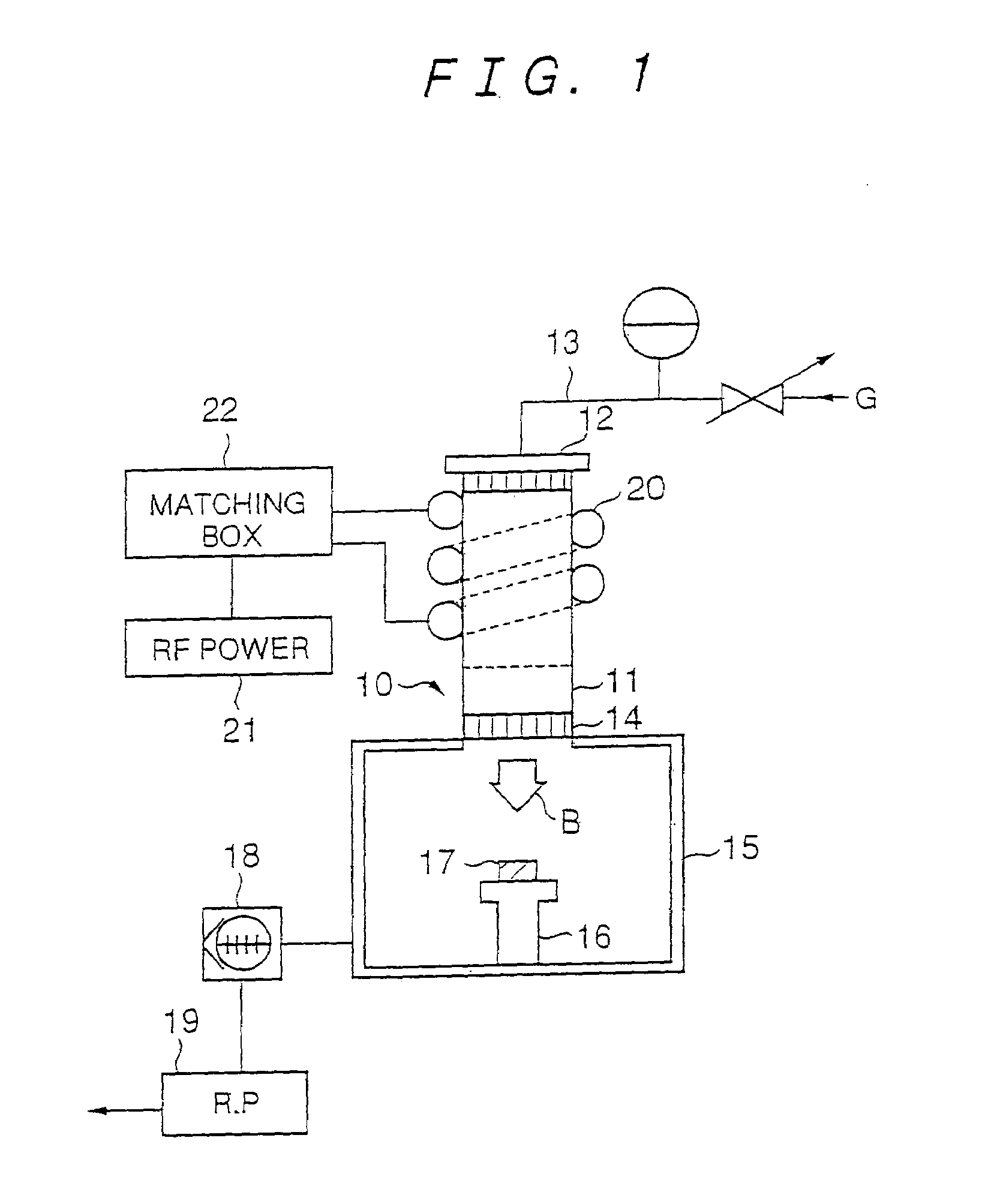
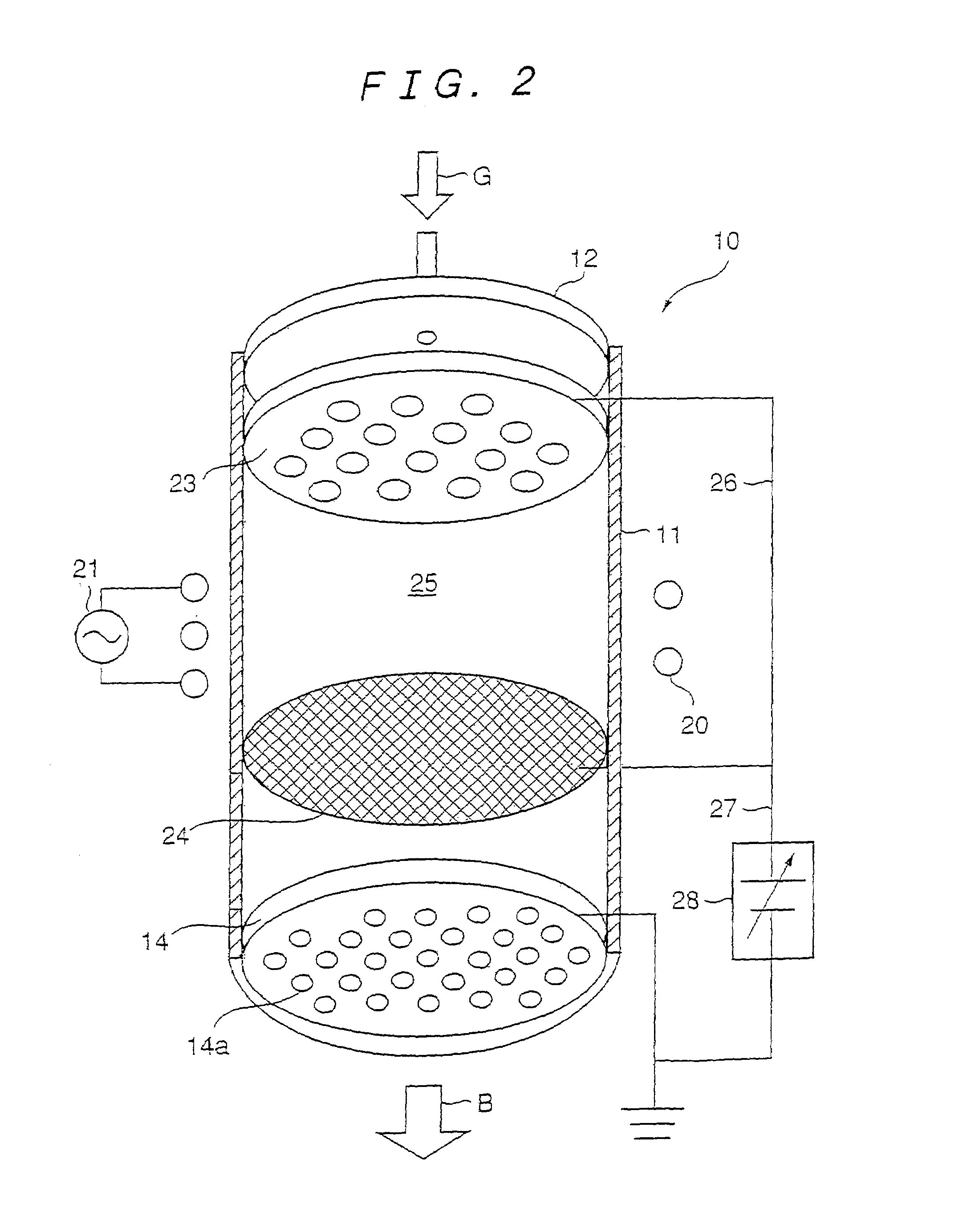
[0026]FIG. 1 is an explanatory diagram showing the overall construction of a processing apparatus employing a beam source according to a preferred embodiment of the present invention. Abeam source 10 comprises a discharge tube 11 and a plasma forming means (a coil 20 and the like) disposed external to the discharge tube 11. The plasma forming means converts gas introduced through a gas inlet 12 into plasma. The inside of the discharge tube 11 and an adjacent chamber 15 are evacuated to form a high vacuum using a turbo-molecular pump 18 and a rotary pump 19. An inductively coupled coil 20 is disposed around the discharge tube 11. A radio-frequency power source 21 supplies an RF power of 13.56 MHz, for example, to the coil 20 via a matching box 22 to convert gas introduced into the discharge tube 11 into plasma. The coil 20 is a water-cooled pi...


PUM


Abstract

An object of the present invention is to provide a beam source capable of efficiently generating a high-density energy beam having good directivity and a relatively large beam diameter. The beam source of the present invention comprises a discharge tube; a gas inlet for introducing gas into the discharge tube; three electrodes mounted in the discharge tube downstream from the gas inlet, wherein the electrode on the upstream end has a plurality of openings through which the gas can pass, the middle electrode is a mesh-shaped electrode, and the electrode on the downstream end is a beam-emitting electrode having a plurality of beam-emitting holes and is disposed in a plane parallel to the middle electrode; plasma-generating means disposed between the two upstream electrodes on the outside of the discharge tube for transforming gas introduced into the discharge tube into plasma; and voltage-applying means for accelerating the beam between the two downstream electrodes and emitting the accelerated beam from the downstream beam-emitting electrode.

Description

TECHNICAL FIELD[0001]The present invention relates to a beam source for generating a high-density ion beam, neutral particle beam, or the like having good directivity from high-density plasma.BACKGROUND ART[0002]In recent years, there has been a remarkable reduction in the size of processing patterns used in semiconductor ICs, data storage media including hard disks, micro-machines, and other fields. Processing technologies, such as deposition and etching, used in these fields now require relatively broad irradiating energy beams such as high-density neutral particle beams or ion beams having high collimation (good directivity). The inventors of the present invention and others have already disclosed beam sources having the following constructions for such applications.[0003]The first type of beam source comprises a discharge tube, a gas feed nozzle disposed upstream from the discharge tube for supplying gas therein, a beam-emitting electrode formed with a plurality of apertures and...

Claims


Application Information

Patent Timeline
Patent Type & Authority Patents(United States)
IPC IPC(8): H01J37/08H01J37/32H01J27/16H05H3/00G21G4/02
CPCH01J27/16H01J37/08H01J37/321H01J37/32192H05H3/00
Inventor HATAKEYAMA, MASAHIROICHIKI, KATSUNORIWATANABE, KENJISATAKE, TOHRU
Owner EBARA CORP
Why Eureka
Try Eureka