Light receiving element, light detector with built-in circuitry and optical pickup

a light receiving element and built-in circuit technology, applied in the direction of optical radiation measurement, radiation controlled devices, instruments, etc., can solve the problems of reducing the response speed of the photodiode, the photodiode is likely to fail to read an address signal immediately, etc., to delay the photoelectric current, the intensity of the internal electric field in this region is increased, and the response speed is reduced

Inactive Publication Date: 2005-09-27
SHARP KK
View PDF3 Cites 14 Cited by
  • Summary
  • Abstract
  • Description
  • Claims
  • Application Information

AI Technical Summary

Benefits of technology

[0074]In one embodiment of this invention, the intensity of an internal electric field in a region in the vicinity of the peak of the impurity concentration of the first, second conductivity type semiconductor layer is increased.
[0086]Thus, the number of photocarriers having a low response speed, which are generated at a site deeper than the narrow region in the vicinity of the peak of the impurity concentration of the first, second conductivity type semiconductor layer within the light receiving element, and are moved over a long distance to an end of the depletion layer (PN junction region) provided at the interface between the second, second conductivity type semiconductor layer and the second, first conductivity type semiconductor layer, can be reduced. Further, the region in the vicinity of the peak of the impurity concentration of the first, second conductivity type semiconductor layer is narrow, and the intensity of the internal electric field in this region is increased. Therefore, photocarriers generated in a portion of the narrow region in the vicinity of the peak of the impurity concentration of the first, second conductivity type semiconductor layer and nearer the second, second conductivity type semiconductor layer can be reliably moved to the depletion layer at the interface between the second, first conductivity type semiconductor layer and the second, second conductivity type semiconductor layer and can be taken as a photoelectric current. As a result, a delayed photoelectric current due to the photocarriers having a long movement time and a low response speed can be substantially reduced, thereby obtaining the photodiode having a much improved response speed with respect to incident light.
[0087]Thus, the invention described herein makes possible the advantages of providing a light receiving element capable of writing data onto an optical disk at high speed in the data write mode of an optical disk apparatus by reducing photocarriers generated in a region deeper than a depletion layer and having a low response time required to be moved to the vicinity of the depletion layer; an light detector with built-in circuitry comprising the light receiving element; and an optical pickup comprising these devices.

Problems solved by technology

The increase in the photocarrier movement time may reduce the response speed of the photodiode.
As the light amount of laser light is increased, the photodiode is likely to fail to read an address signal immediately after writing data onto the optical disk in the write mode.
This is a large problem when a higher data write speed is desired.

Method used


Image

  • Light receiving element, light detector with built-in circuitry and optical pickup
  • Light receiving element, light detector with built-in circuitry and optical pickup
  • Light receiving element, light detector with built-in circuitry and optical pickup

Examples


example 1

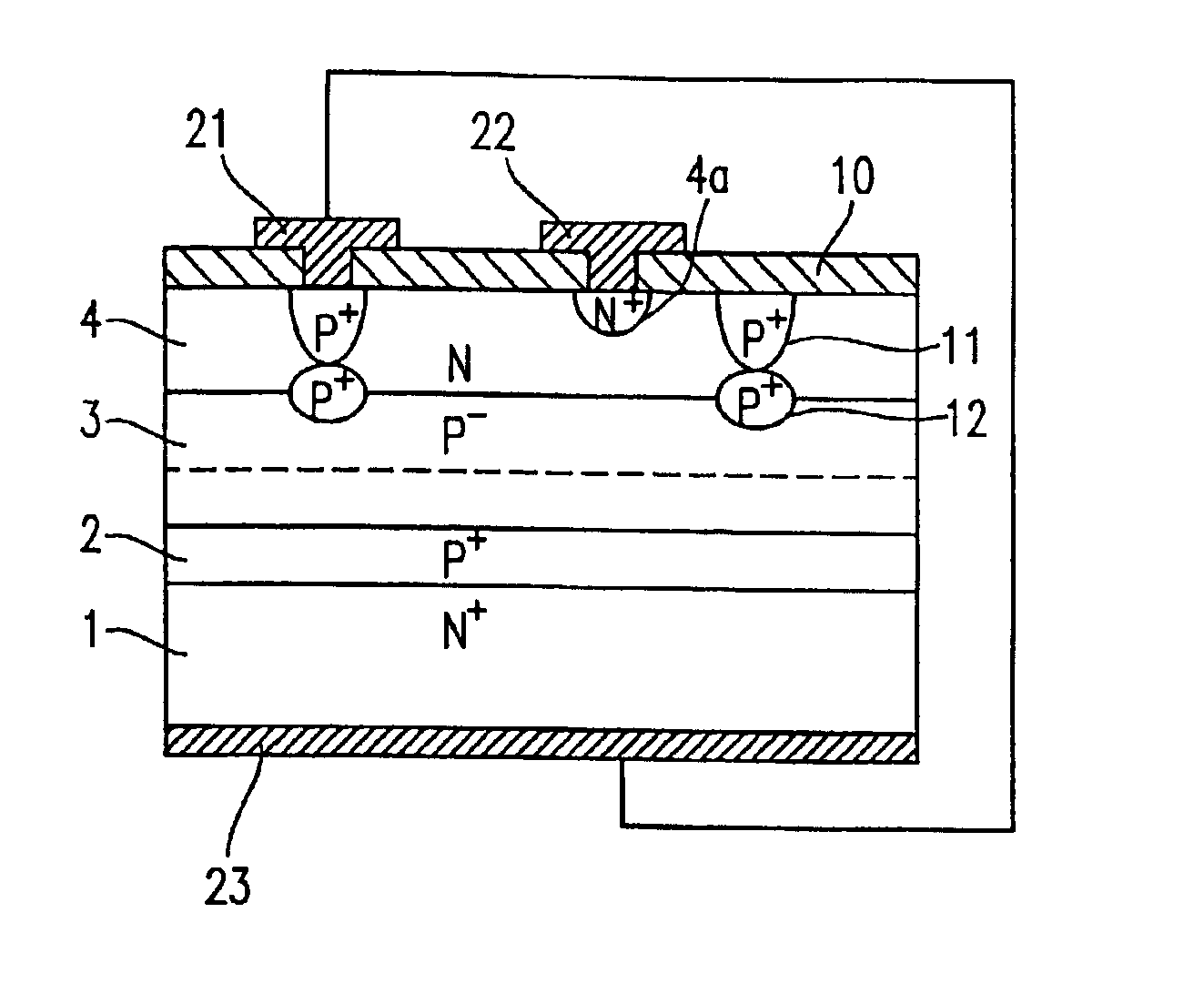
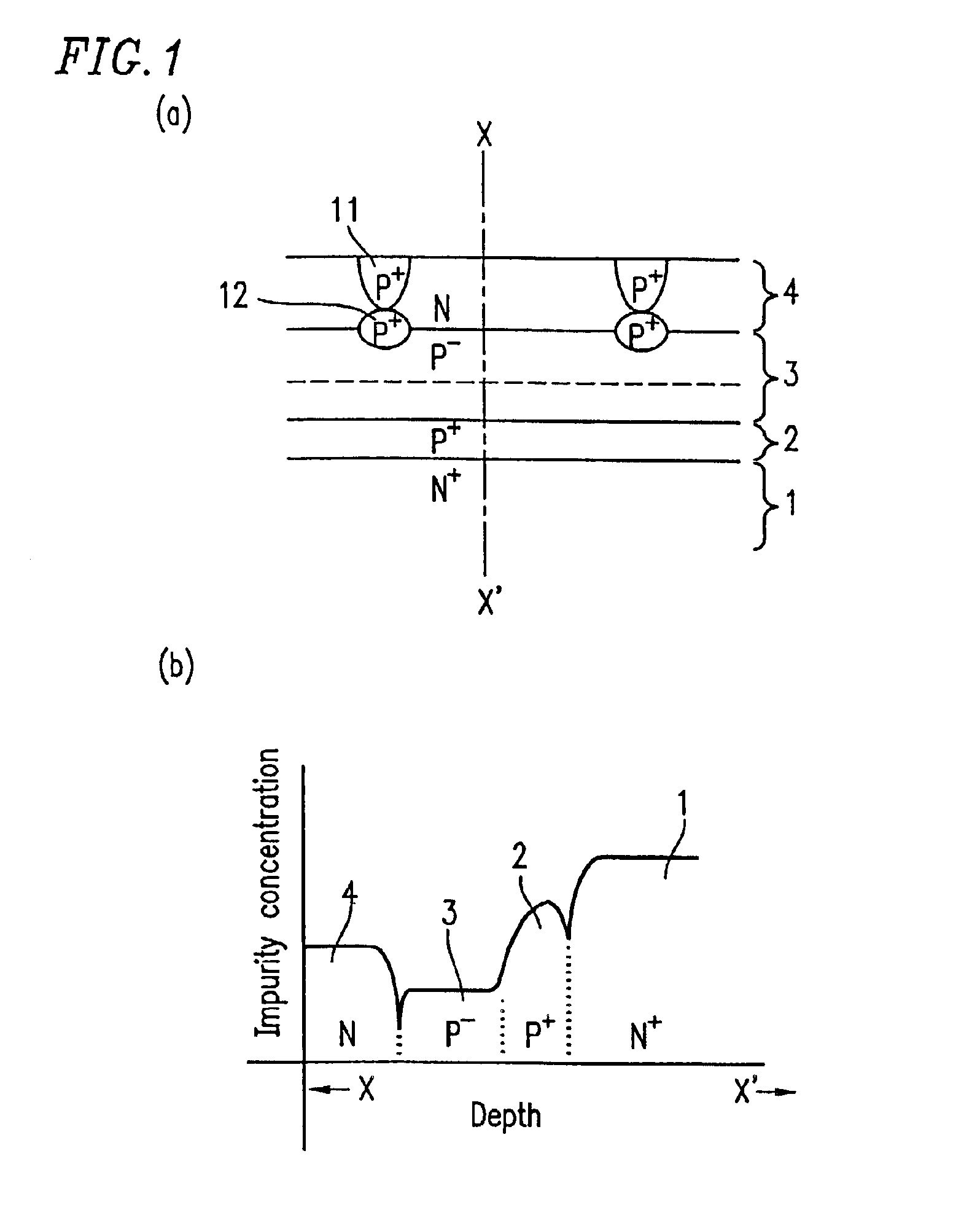
[0109]FIG. 1A is a cross-sectional view showing a light receiving element (photodiode) according to Example 1 of the present invention. FIG. 1B is a graph showing the impurity concentration on a cross section of the photodiode, taken along line X-X′ in FIG. 1A. Note that in FIG. 1A, an anode electrode, a cathode electrode, signal lines and a surface protection film are not shown.

[0110]The photodiode of FIG. 1A comprises an N+-type semiconductor substrate 1 (first conductivity type semiconductor substrate) having a high impurity concentration, and a P+-type buried diffusion layer 2 (first, second conductivity type semiconductor layer) having a lower impurity concentration than that of the substrate 1, a high resistivity P-type epitaxial layer 3 (second, second conductivity type semiconductor layer) having a lower impurity concentration than that of the P+-type buried diffusion layer 2, and an N-type epitaxial layer 4 (second, first conductivity type semiconductor layer),which are lam...

example 2

[0145]FIG. 4A is a cross-sectional view showing a structure of a light receiving element (photodiode) according to Example 2 of the present invention. FIG. 4B is a graph showing the impurity concentration on a cross section of the photodiode, taken along line Y-Y′ in FIG. 4A. Note that in FIG. 4A, an anode electrode, a cathode electrode, signal lines and a surface protection film are not shown.

[0146]The photodiode shown in FIG. 4A comprises a semiconductor structure comprising a low resistivity P-type semiconductor substrate 7 (second conductivity type semiconductor layer), and an N++-type buried diffusion layer 6 (first conductivity type semiconductor layer) thereon, which has a higher impurity concentration than that of the low resistivity P-type semiconductor substrate 7. On the N++-type buried diffusion layer 6, a P+-type buried diffusion layer 2 having a lower impurity concentration than that of the N++-type buried diffusion layer 6, a high resistivity P-type epitaxial layer 3 ...

example 3

[0164]FIG. 5A is a cross-sectional view showing a structure of a light receiving element (photodiode) according to Example 3 of the present invention. FIG. 5B is a graph showing the impurity concentration on a cross section of the photodiode, taken along line Z-Z′ in FIG. 5A. Note that in FIG. 5A, an anode electrode, a cathode electrode, signal lines and a surface protection film are not shown.

[0165]The photodiode shown in FIG. 5A comprises a semiconductor structure comprising a low resistivity N-type semiconductor substrate 5 (first conductivity type semiconductor layer), and an N++-type buried diffusion layer 6 (first conductivity type semiconductor layer) thereon, which has a higher impurity concentration than that of the low resistivity N-type semiconductor substrate 5. On the N++-type buried diffusion layer 6, a P+-type buried diffusion layer 2 having a lower impurity concentration than that of the N++-type buried diffusion layer 6, a high resistivity P-type epitaxial layer 3 h...


PUM

PropertyMeasurementUnit
thicknessaaaaaaaaaa
resistivityaaaaaaaaaa
photoelectric currentaaaaaaaaaa

Abstract

A light receiving element, comprising a semiconductor structure comprising at least a first conductivity type semiconductor layer, a first, second conductivity type semiconductor layer provided on the first conductivity type semiconductor layer in the semiconductor structure, a second, second conductivity type semiconductor layer having an impurity concentration lower than that of the first, second conductivity type semiconductor layer, a second, first conductivity type semiconductor layer provided on the second, second conductivity type semiconductor layer, or a second, first conductivity type semiconductor layer provided within the second, second conductivity type semiconductor layer.

Description

BACKGROUND OF THE INVENTION[0001]1. Field of the Invention[0002]The present invention relates to a light receiving element for use in writing data to, and reading data from, an optical disk, such as CD-R / RW, DVD-RAM, or the like. The present invention also relates to a light detector comprising the light receiving element and built-in circuitry, and an optical pickup comprising the light detector.[0003]2. Description of the Related Art[0004]Photodiodes (PDs), which are light receiving elements, are semiconductor devices which convert incident light through their light receiving surfaces to an electrical signal. The PDs are used for optical pickups of optical disk apparatuses which write data onto an optical disk, such as CD-R / RW, DVD-R / RW, DVD-RAM, or the like.[0005]FIG. 12 is a schematic diagram showing a configuration of an optical pickup comprising a photodiode. This optical pickup comprises a semiconductor laser (laser diode) LD for irradiating a predetermined portion of the inf...

Claims


Application Information

Patent Timeline
Patent Type & Authority Patents(United States)
IPC IPC(8): G01J1/02G11B7/00H01L27/14H01L31/06H01L31/10H01L31/00G11B7/13H01L31/103
CPCG11B7/13H01L31/103G11B7/133H01L27/14H01L31/10
Inventor TAKIMOTO, TAKAHIROOHKUBO, ISAMUKUBO, MASARUNAKAMURA, HIROKIFUKUSHIMA, TOSHIHIKOYOSHIKAWA, TOSHIFUMI
Owner SHARP KK
Why Eureka
Try Eureka