
Electronic time-temperature indicator

a technology of time-temperature indicators and indicators, which is applied in the direction of heat measurement, fire alarms, instruments, etc., can solve the problems of low stability of materials that deteriorate quickly in response to higher temperatures, and have a tendency to deteriorate, so as to achieve easy and precise customization, simple visual output, and instant assessment of material fitness.

Inactive Publication Date: 2005-09-27
ZWEIG STEPHEN ELIOT
View PDF13 Cites 90 Cited by
  • Summary
  • Abstract
  • Description
  • Claims
  • Application Information

AI Technical Summary

Benefits of technology

"The present invention is an improved electronic time-temperature indicator that can be customized to match the thermal degradation profile of any material. It allows for precise characterization of the material's thermal history and can instantly assess its fitness for use. The indicator is unitized, meaning all components are designed to be a single hand-held unit, and can operate without the need for any additional components or external connections. The display of the indicator is easy to read, indicating if the material is still acceptable or not, and may also show the approximate storage life remaining on the material or the probable cause as to why it has expired."

Problems solved by technology

That is, the materials have a tendency to deteriorate with time, and this tendency to deteriorate is often accelerated by exposure to higher temperatures.
By contrast, a material that deteriorates quickly in response to higher temperatures is said to have a “low stability”.
Excessive deterioration eventually results in the material in question being rendered unfit to use, or even rendered dangerous.
Since curing, incubation, or heat treatment processes are often temperature dependent, typically taking longer to proceed at lower temperatures, such materials must undergo a certain minimal time-temperature history before they are fit for use.
However upon exposure to an excessive amount of temperature for an excessive amount of time, the center of the bull's eye becomes darker than the surrounding area.
If the strip does not show a proper level of color change, than the material has not been exposed to an adequate level of temperature and time necessary to assure sterility.
This indicator combines a passive RFID unit with an enzyme based degradable circuit component, such that as the indicator is exposed to excessive amounts of temperature for excessive amounts of time, the RFID signature of the tag changes.
Although this approach lends itself to very low cost time-temperature sensors, the lack of visual output is inconvenient for most users, who typically are not equipped with sophisticated RFID reading equipment.
As a result, users without this specialized equipment will be unable to ascertain the status of the sensor.
An additional drawback of Sjoholm et. al. is that the precise stability characteristics of this device are dependent upon tuning the specific degradation of a chemically based (enzymatic) time-temperature sensor to match the degradation characteristics of an arbitrary product.
This is a time-consuming and burdensome process that may not always result in a precise stability match between the characteristics of the chemical time-temperature indicator, and the characteristics of the monitored material.
However data loggers of prior art do not attempt to interpret this detailed history.
It is clear that such devices impose a considerable burden on unsophisticated users, who simply want to know if the material associated with the device is appropriate for use or not.
More specifically, however, the device of Re 36,200 may be viewed as a limited type of integrating time-temperature indicator, in that this device uses a sensor (isolated and protected from the external environment by a housing that also contains the other circuit components) to generate the time integral of temperature outside of an acceptable range, or above or below a predetermined threshold temperature, and store or otherwise make use of this value for output purposes.
In particular, the method is generally incapable of realistically modeling (or simulating) material thermal stability profiles, and thus is prone to generate inaccurate results.
This method is very simplistic, however.
As will be discussed in more detail later on, most materials have much more complex thermal degradation profiles, and are poorly monitored by such simplistic approaches.
This second type also monitors the time and temperature by chemical or electronic means, but does not output the data in a manner that is readily accessible to unsophisticated users without additional equipment.
Such devices are useful for monitoring conditions during shipping, such as determining if shipment ice packs have melted, detecting if a shipping container has been exposed to temperatures over 50° C., or detecting other standard shipping faults, but are less useful for monitoring the individualized stability profiles of arbitrary materials.
The time-temperature devices of prior art thus have a number of significant drawbacks.
They are either hard to read, inaccurate, or both.
Most material recipients are not sophisticated in the details of the precise thermal time-temperature degradation profile of the materials they have just received.
The visual indicators of prior art, which are chemically mediated, give immediate visual results, but are not particularly accurate.
The drawback of this chemical approach, however, is that most materials of interest, such as biological materials, often may have unique and complex time-temperature profiles.
By contrast, however, there are only a limited number of sensor chemicals that are suitable for visual time-temperature indicators.
It is often difficult or impossible to find an exact match, over all temperatures, between the degradation rate of the sensor chemical, and the degradation rate of the material of interest.
Although this scenario will insure that the user does not inadvertently accept degraded material, it is inefficient.
In many cases, material that is, in fact, still good may be inappropriately discarded due to poor time-temperature indicator accuracy.
Of course, the alternative scenario, in which the chemical time-temperature indicator fails to adequately warn that the tracked material is degraded, is both unacceptable and potentially dangerous.
By contrast, electronic data loggers have a different set of problems.
Although these devices collect a full set of accurate time-temperature data, which may be used to determine if a material is acceptable or not, the data is in a difficult to interpret form.
As previously discussed, many or most material recipients are unsophisticated, and are unlikely to have the equipment or specialized knowledge in order to read an electronic device, or to interpret a complex chart-recorder graphical output.
As a result, many unsophisticated users, receiving material associated with an unreadable or hard-to-read electronic tag, are likely to ignore the tag altogether.
As a result, users may inadvertently use material that has been degraded by an unacceptable thermal history.
The temperature alarms of the prior art, such as U.S. Re. 36,200, also are not ideal.
These alarms can only be adjusted to trigger on a limited set of fixed unacceptable temperature for a fixed unacceptable time combinations.
They are not well suited to accurately mimic the stability characteristics of arbitrarily selected materials.
As a result, they have a tendency to either trigger too soon, or too late, which can result in either waste, or inadequate warning.

Method used

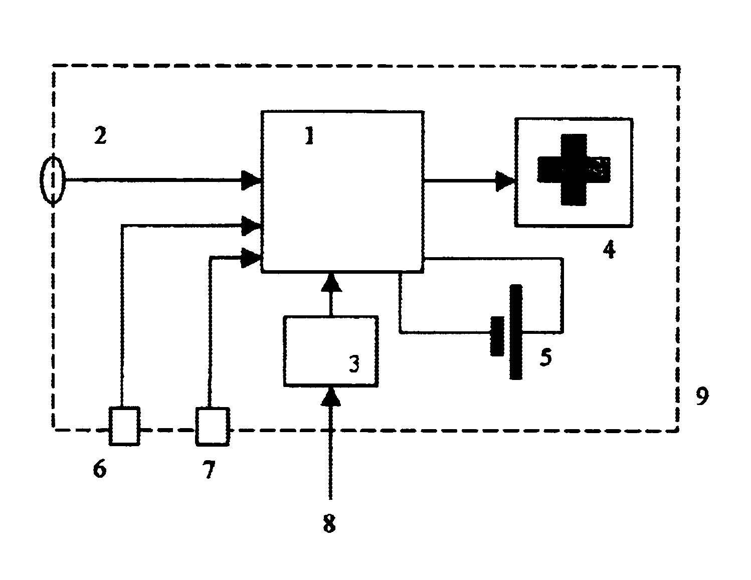
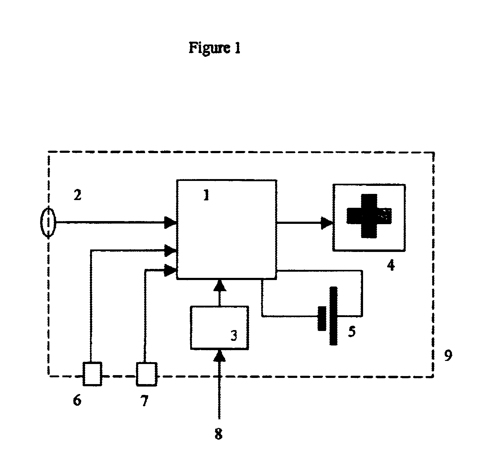

Image

  • Electronic time-temperature indicator
  • Electronic time-temperature indicator
  • Electronic time-temperature indicator

Examples


example 1

Insulin Time Temperature Monitor

[0120]In order to properly configure the device, the stability of the material of interest should first be characterized. To do this, quantitative “maximum acceptable deterioration” criteria, should be established, and used to determine the material's stability lifetime when the material is stored at a variety of different temperatures. The stability lifetime at the various experimental temperature levels is then determined, and used as input into the stability programming calculations.

[0121]Using the experimental data, a curve or equation is then generated that fits the observed data. This curve is used to calculate the stability lifetime at intermediate temperatures.

[0122]As an example, consider a commonly used injectable drug, insulin. Insulin is commonly carried by traveling diabetics, but will deteriorate if exposed to excessive levels of temperature for too long. The work of Brange et. al. ‘Galenics of Insulin’ [Novo Research Institute, Denmark]...

example 2

Other Drug Monitoring Applications

[0159]There are a number of medically important antibiotics, such as the P-Lactam antibiotics (which include Ceftazidime, Cefepime, Imipenem, Meropenem, Cefpirome, and others), which would be most effective if the drugs could be administered by continuous infusion to ambulatory patients. Such continuously infused antibiotics would be highly useful for treating cystic fibrosis, immunocompromised chemotherapy patients (who are at risk for sepsis), and many other conditions.

[0160]However due to the poor thermal stability of the β-Lactam antibiotics, current continuous infusion pump (either mechanical or elastomeric) technology is inadequate. In the liquid form, many of the β-Lactam drugs deteriorate after only a few hours of exposure to temperatures above 25° C. Since body temperature is 37° C., conventional ambulatory infusion pumps, which usually are worn underneath clothing, typically expose such drugs to unacceptable levels of thermal stress.

[0161]...


PUM

PropertyMeasurementUnit
temperatureaaaaaaaaaa
time resolutionaaaaaaaaaa
temperature resolutionaaaaaaaaaa

Abstract

This invention covers electronic time-temperature indicators with a visual output, and other devices and methods by which the thermal history of a material may be monitored, and the subsequent fitness for use of the tracked material may be quickly ascertained. In particular, the invention discloses a rapidly reprogrammable electronic time-temperature tag that may be easily customized with the thermal time-temperature stability profile of an arbitrary material, using electronic data transfer methods. Using this device, a single, low-cost, generic time-temperature tag may be mass-produced, and then subsequently programmed to mimic the stability characteristics of nearly any material of interest.

Description

[0001]This application claims the priority benefit of provisional patent application 60 / 465,434, “Electronic time-temperature indicator”, filed Apr. 25, 2003.BACKGROUND OF THE INVENTION[0002]1. Field of the Invention[0003]This invention covers electronic time-temperature indicators with a visual output, and other devices and methods by which the thermal history of a material may be monitored, and the subsequent fitness for use of the tracked material may be quickly ascertained by visual or other means.[0004]2. Description of the Related Art[0005]Many materials in use in commerce, medicine, and other areas are perishable. That is, the materials have a tendency to deteriorate with time, and this tendency to deteriorate is often accelerated by exposure to higher temperatures. This tendency to deteriorate is often designated as a material's “stability”. A material that deteriorates slowly in response to higher temperatures over long periods of time is said to have a “high stability”. By...

Claims


Application Information

Patent Timeline
Patent Type & Authority Patents(United States)
IPC IPC(8): G01K3/00G01K3/04
CPCG01K3/04G06K19/0717
Inventor ZWEIG, STEPHEN ELIOT
Owner ZWEIG STEPHEN ELIOT
Learn More