
Fine moire correction in images

a moire correction and image technology, applied in the field of image data, can solve the problems of troublesome viewing, undesirable moiré patterns, and the inability to distinguish between noise and image edges, and achieve the effect of reducing moiré in images

Active Publication Date: 2005-09-27
COREL CORP +1
View PDF48 Cites 23 Cited by
  • Summary
  • Abstract
  • Description
  • Claims
  • Application Information

AI Technical Summary

Benefits of technology

[0039]As can be seen, the main emphasis on the reduction of moiré patterns, both in printed and monitor images has been directed towards breaking up the relative frequencies between overlying or contiguous patterns. It is desirable to find alternative methods of reducing moiré in images, particularly within software solutions.

Problems solved by technology

These techniques do not however distinguish between noise and image edges as far as enhancement is concerned, and the higher the density Di or D the greater the enhancement.
However, there arises a problem in reading an original image such as a photograph or a painting having thick portions and thin portions provided as a dot image by a half tone etching method.
More specifically, because of the relation between the pitch between each of the dots and the reading pitch by the image pickup device, or of a subtle deviation of phase based on the period and the like in half tone processing, a periodical pattern of thick and thin portions called moiré pattern is generated, providing trouble in viewing.
Examples of undesirable moiré patterns are those formed in computer monitors or by overlap of color separations in color printing.
One area in which moiré is a particular problem is in digital imaging, where images are formed as regular grids of picture elements or pixels.
Typically, the scanner contains a detector such as a CCD (Charge Coupled Device) array and the spacing of the array interacts with the spacing of ink dots to produce an undesirable moiré pattern in the scanned image.
Thus, approaches for removing moiré using blurring are completely unsuitable for removing this type of defect since blurring sufficient to reduce the bands will completely destroy small, and often medium scale, detail in the image.
No generally applicable and straightforward methods exist for achieving this objective.
This approach does not admit automation and requires that there must first be available a method of editing look-up tables, something not normally found in consumer software.
In practice it is very difficult to accomplish the disclosed correction in a way that leaves the edges of bands looking natural and blended with the image.
Another disadvantage of this method of band elimination is that, while the alteration may lead to reduction in banding, it also influences the same color channel in regions of the image where there is no banding.
This introduces new defects.
A further disadvantage of this approach is that it reduces the total number of colors in the image.
In summary, the success of the published procedure depends very much on the specific image content, requires great skill and familiarity with image processing concepts, must be accomplished by time-consuming region-by-region correction of the image, and cannot be automated.
In some examples of consumer scanners (as noted in X. Liu and R. Erich, Image Vis. Comput., v.18(10), 843-8 (2000)) non-uniform resampling of the image in the scanner introduces extra aliasing components and complicates the moiré pattern.
However, the moiré pattern cannot be eliminated by this method when the reading pitch (the pitch between pixels in the image pickup device) itself is the cause of the moiré pattern.
However, the moiré pattern cannot be eliminated in all of the images having thick portions and thin portions even by this method when a plurality of images with thick portions and thin portions having different dot pitches are included in the original image.
Accordingly, when intensity change of the original image has periodicity such as in a half tone image, there is a possibility of formation of moiré in a recorded image due to interference of the periodicity of the intensity change of the original image with the pitch of the image sensor arranged in the line sensor, that is, the sampling period.
However, when intensities of a plurality of pixels are averaged to eliminate a moiré, the resultant character image or continuous-tone image may be undesirably blurred.
Therefore, there is a problem in that when a mesh image and a character image or a continuous-tone image are mixed in one original image, the averaging process must be applied only to the mesh image area.
However, such methods have been associated with the following drawbacks: (1) if the original image is a screen-tone image such as a printed image, the copied image may show stripe patterns which do not exist in the original image; and (2) if the original image contains line-tone images or characters, the image quality may be deteriorated as the edges are broken by the dither method.
Hence, the ideal case typically cannot practicably be realized.
In fact, the closer the spatial frequency and the spot frequencies are to each other, the lower the moiré beat frequency νMoire and the more visible and objectionable the moiré interference pattern becomes.
From an operating standpoint, the moiré interference phenomenon poses a serious aesthetic problem, since the best electron beam focus and highest image resolution results in unacceptably noticeable moiré patterns if the video signal being displayed includes alternating pixel patterns, which is a common occurrence.
The lower amplitude spot sinusoid results in a decrease of the amplitude, and therefore visibility, of the resulting moiré interference.
When viewed by a user of the CRT, optical cancellation of the moiré interference patterns results.

Method used


Image

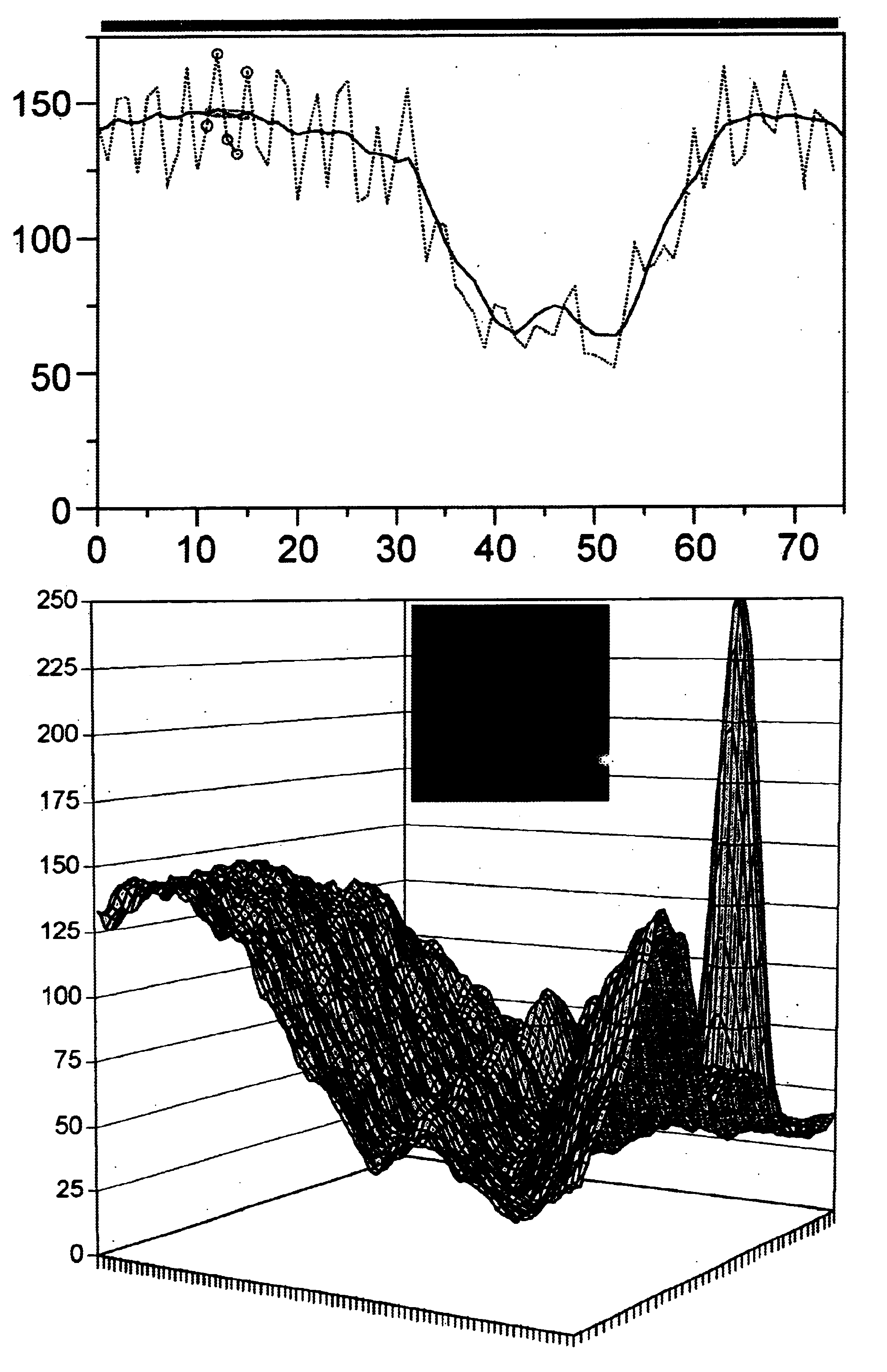
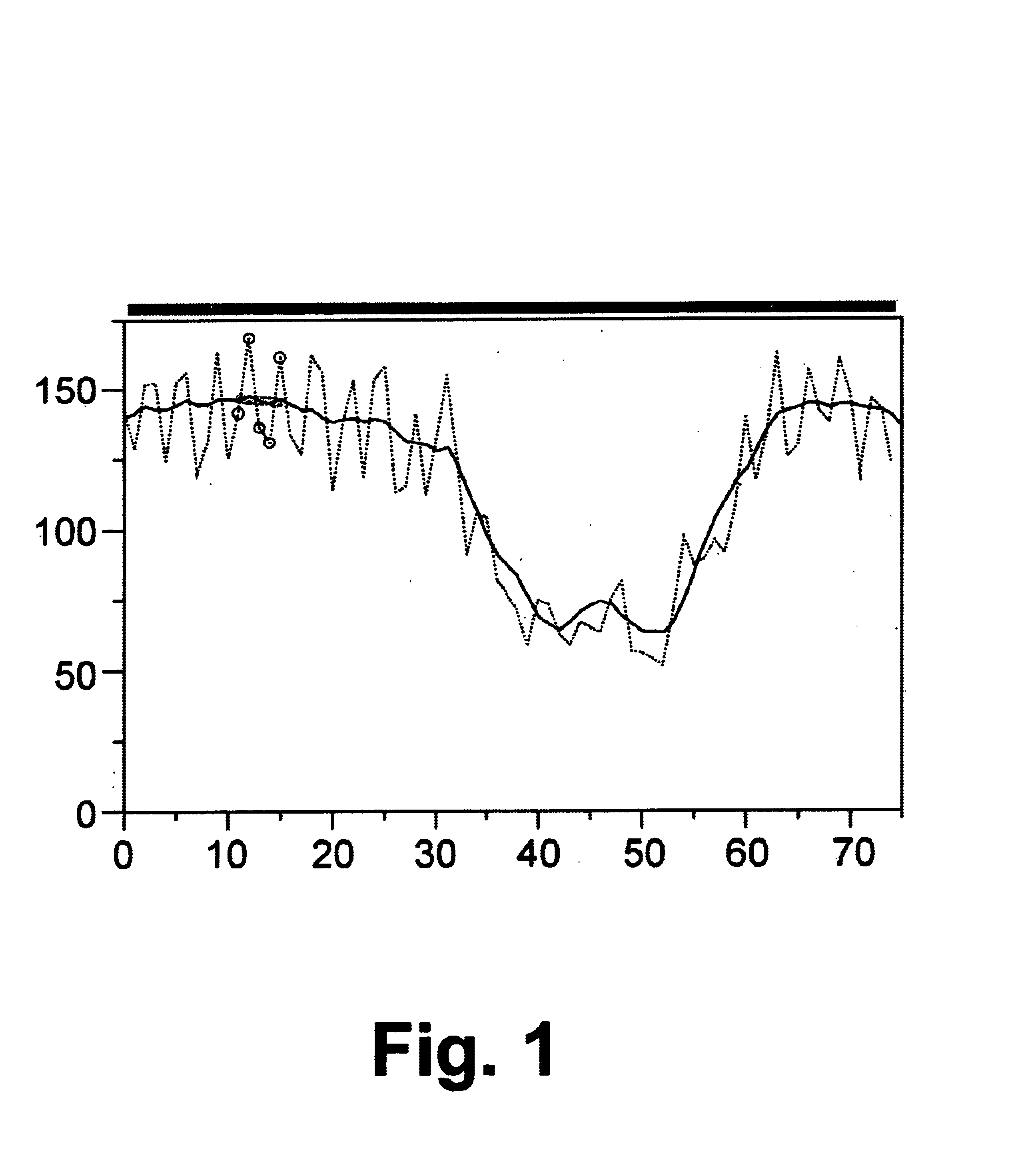
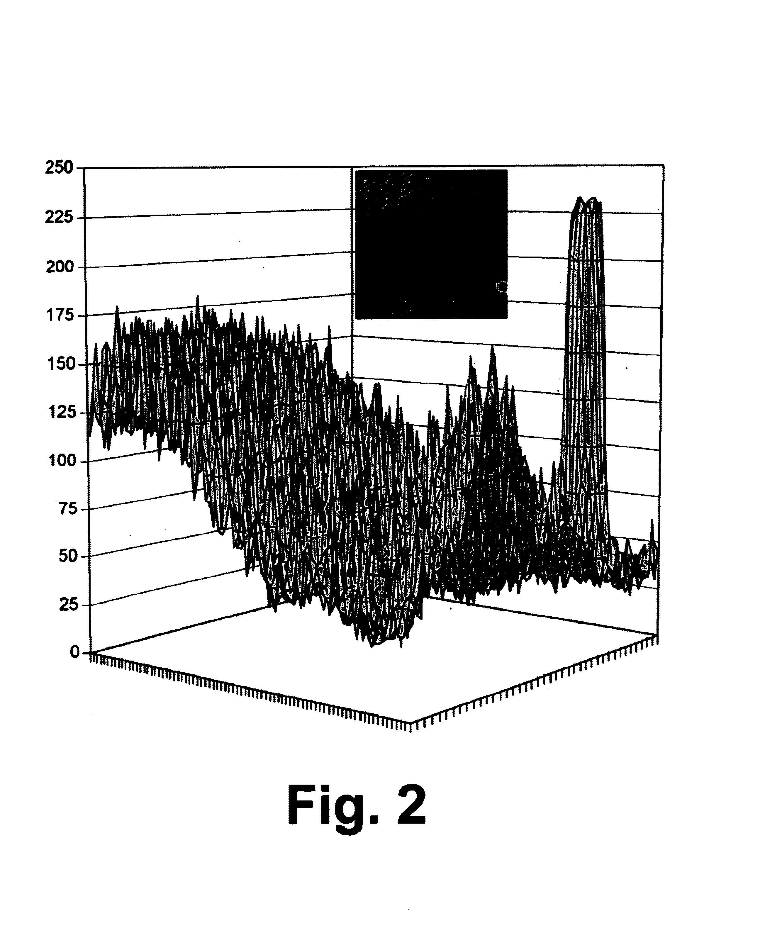
  • Fine moire correction in images
  • Fine moire correction in images
  • Fine moire correction in images

Examples


Embodiment Construction

[0046]The practice of this invention operates on digital images. A digital image comprises a collection of picture elements or pixels arranged on a regular grid. A gray scale image is represented by a channel of specific brightness values at individual pixel locations. Such a channel may also be represented as a color palette, for example containing 256 shades of gray. Gray scale images contain only achromatic colors, in other words those colors without a specific hue and with a zero saturation. A color image contains several channels, usual three or four, to describe the color at a pixel. For example, there may be red, green and blue (RGB) channels, or cyan, magenta, yellow and black (CMYK) channels. Each channel again contains brightness values representing the amount of color at each pixel. A color image may also be represented in palettized form. Such images contain chromatic colors, which possess both hue and saturation. The invention is concerned with both monochromatic images...


PUM


Abstract

A method of noise removal from a digital image, especially moiré noise, comprising providing a three-dimensional representation of a at least one image color channel as a surface over the plane of the image, creating a virtual surface patch, placing the surface patch against topography in the three-dimensional surface mapping of the image so that the virtual surface patch intersects topography of the three-dimensional surface with respect to at least some pixels of the image surface region, adjusting the height, tilt and curvature of the surface patch with respect the image surface in order to optimally represent the surface, then estimating a palliative value for the image surface for at least one pixel within the area of the surface patch from the adjustment of the surface patch, and replacing the value of the at least one pixel in the at least one image color channel with the palliative value.

Description

BACKGROUND OF THE INVENTION[0001]1. Field of the Invention[0002]The present invention relates to image data, particularly image data that is provided as an image file, and particularly image data that generates an image and may contain moiré patterns, particularly color images that display moiré patterns in virtual or real images.[0003]2. Background of the Art[0004]Recorded images comprise a spatial, normally planar, representation of either spatially or temporally variable original signals. A large proportion of such recordings, such as copies of documents and pictures, represent a one-to-one relationship with an original document or scene, frequently with magnification or reduction involved. Radiographic film images in medicine represent a class of images where the original is not visible to the human eye and must be formed by a combination of invisible radiation (e.g., x-rays) and a suitable transducer (fluorescent screen).[0005]In all image forming systems, degradation of the or...

Claims


Application Information

Patent Timeline
Patent Type & Authority Patents(United States)
IPC IPC(8): G06T5/00
CPCG06T5/002G06T5/20G06T2207/10024G06T5/70
Inventor TRIFONOV, MIKHAIL IVANOVICHZAKLIKA, KRYZSTOF ANTONIGRUZDEV, PAVEL VLADIMIROVICH
Owner COREL CORP
Learn More