Active fly height control crown actuator

Inactive Publication Date: 2005-09-27
WESTERN DIGITAL TECH INC
View PDF3 Cites 269 Cited by
  • Summary
  • Abstract
  • Description
  • Claims
  • Application Information

AI Technical Summary

Benefits of technology

[0028]The adjustment of the slider crown and/or camber enables the fly height to be actively controlled, whereby a positive crown and/or negative camber would cause the magnetic read/write transducer to move farther from the surface of the magnetic recording disk and vice versa. This motion thus compensates for any pole tip protrusion and thermally induced slider crown caused by the thermal expansion effect. The novel design can also permit a gross adjustment of the fly height to a suitable value as needed.
[0029]The advantages of this novel slider design lie in the effec

Problems solved by technology

However, in the conventional slider design with a near zero fly height, these advantages may not be fully realized due to a number of technical problems imposed by the operation of the magnetic read/write head with near zero fly height.
One such problem is the possibility of the read/write transducer coming into contact with the magnetic recording disk, which may consequently result in a catastrophic failure of the entire magnetic disk drive or head crash.
During a typical operation, the magnetic read/write head is subjected to various thermal sources that can adversely affect the magnetic read/write head.
The temperature increase consequently causes a thermal expansion of the pole tip region of the magnetic read/write head in all directions, but most adversely in the direction toward the magnetic recording disk.
These thermal expansions, in effect, reduce the fly height, and in the worst-case results in a physical contact of the read/write transducer that causes a catastrophic failure of the magnetic disk drive.
Yet another problem also related to the near zero fly height is the altitude sensitivity of magnetic disk drives.
Consequently, the magnetic read/write head operates at a less than optimal fly height since the slider is not sufficiently lifted above the

Method used


Image

  • Active fly height control crown actuator
  • Active fly height control crown actuator
  • Active fly height control crown actuator

Examples


Embodiment Construction

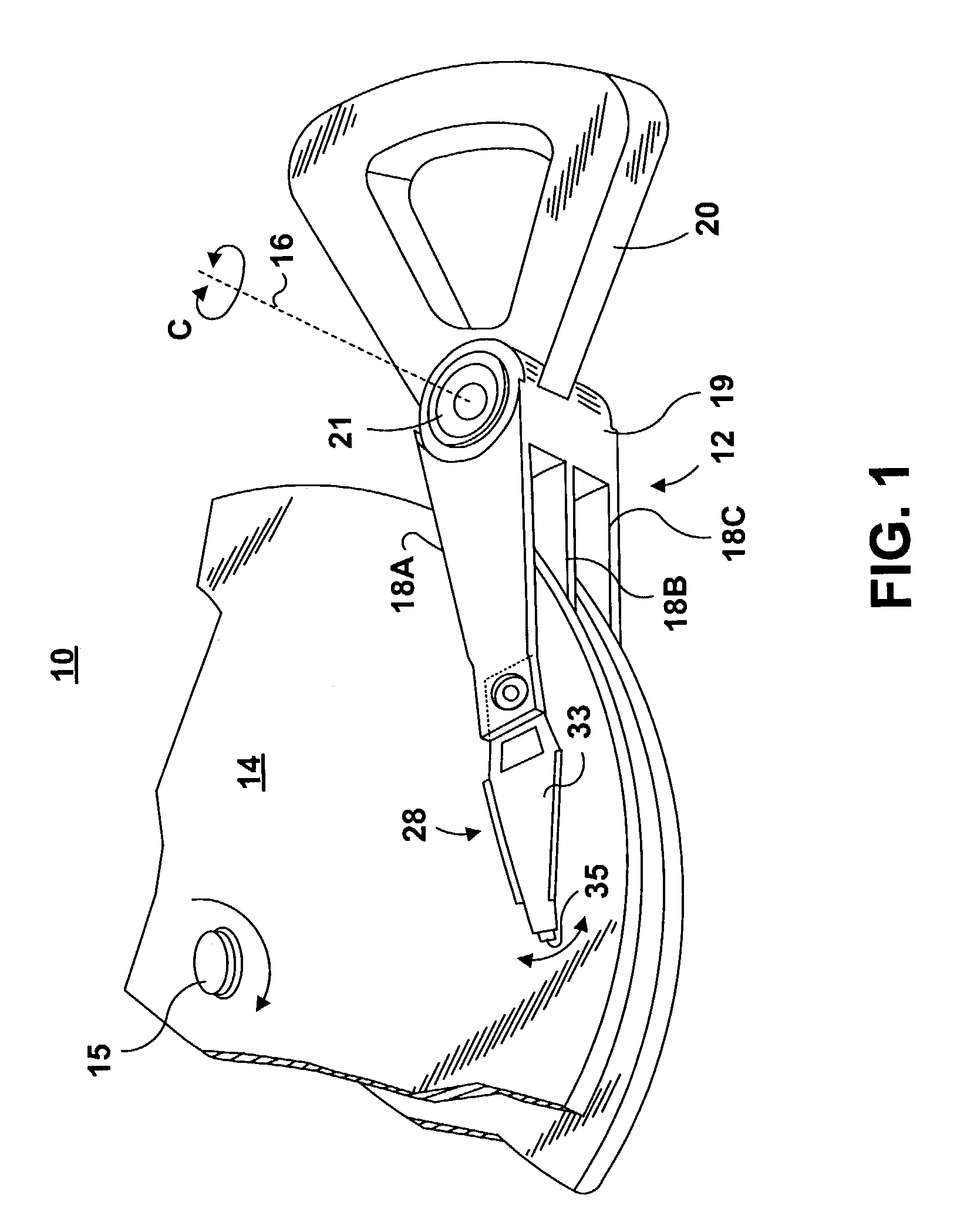
[0059]FIG. 1 illustrates a disk drive 10 comprised of a head stack assembly 12 and a stack of spaced apart smooth media magnetic data storage disks or smooth media 14 that are rotatable about a common shaft 15. The head stack assembly 12 is rotatable about an actuator axis 16 in the direction of the arrow C. The head stack assembly 12 includes a number of actuator arms, only three of which 18A, 18B, 18C are illustrated, which extend into spacings between the disks 14.

[0060]The head stack assembly 12 further includes an E-shaped block 19 and a voice coil 20 attached to the block 19 in a position diametrically opposite to the actuator arms 18A, 18B, 18C. The voice coil 20 cooperates with a magnetic circuit (not shown), comprising in total a voice coil motor (VCM) for rotating in an arc about the actuator axis 16. Energizing the voice coil 20 with a direct current in one polarity or the reverse polarity causes the head stack assembly 12, including the actuator arms 18A, 18B, 18C, to ro...


PUM


Abstract

A micro-actuator is comprised of a piezoelectric motor mounted on a flexure tongue with offsetting hinges, to perform a fine positioning of the magnetic read/write head. The substantial gain in the frequency response greatly improves the performance and accuracy of the track-follow control for fine positioning. The simplicity of the enhanced micro-actuator design results in a manufacturing efficiency that enables a high-volume, low-cost production. The micro-actuator is interposed between a flexure tongue and a slider to perform an active control of the fly height of the magnetic read/write head. The induced slider crown and camber are used to compensate for thermal expansion of the magnetic read/write head, which causes the slider to be displaced at an unintended fly height position relative to the surface of the magnetic recording disk. The enhanced micro-actuator design results in reduced altitude sensitivity, ABS tolerances, and reduced stiction. The controlled fly height of the magnetic read/write head prevents a possibility of a head crash, while improving the performance and data integrity.

Description

PRIORITY CLAIM[0001]The present application claims the priority of U.S. provisional patent application Ser. No. 60 / 421,727, filed on Oct. 28, 2002, titled “Active Fly Height Control Crown Actuator,” which is assigned to the same assignee as the present application, and which is incorporated herein by reference.FIELD OF THE INVENTION[0002]The present invention relates in general to data storage systems such as disk drives, and it particularly relates to a read / write head, such as a thin film head, a MR head, or a GMR head for use in such data storage systems. More specifically, the present invention provides a novel design of a micro-actuator, such as a piezoelectric micro-actuator, that is interposed between a flexure tongue and a slider to perform an active control of the fly height of the magnetic read / write head.BACKGROUND OF THE INVENTION[0003]In a conventional magnetic storage system, a magnetic head includes an inductive read / write transducer fabricated on a slider. The magnet...

Claims


Application Information

Patent Timeline
IPC IPC(8): G11B20/02G11B5/60G11B5/55
CPCG11B5/5552
Inventor MCCASLIN, MARTIN JOHNYOUNG, KENNETHLI, WEIJINKAM, KAH YUENNIU, YIMIN
Owner WESTERN DIGITAL TECH INC
Why Eureka
Try Eureka