[0017]The present invention offers advantages and alternatives over the prior art by providing a split-cycle engine in which significant parameters are optimized for greater efficiency and performance. The optimized parameters include at least one of
Expansion Ratio,
Compression Ratio,
top dead center phasing,
crossover valve duration, and overlap between the
crossover valve event and combustion event.
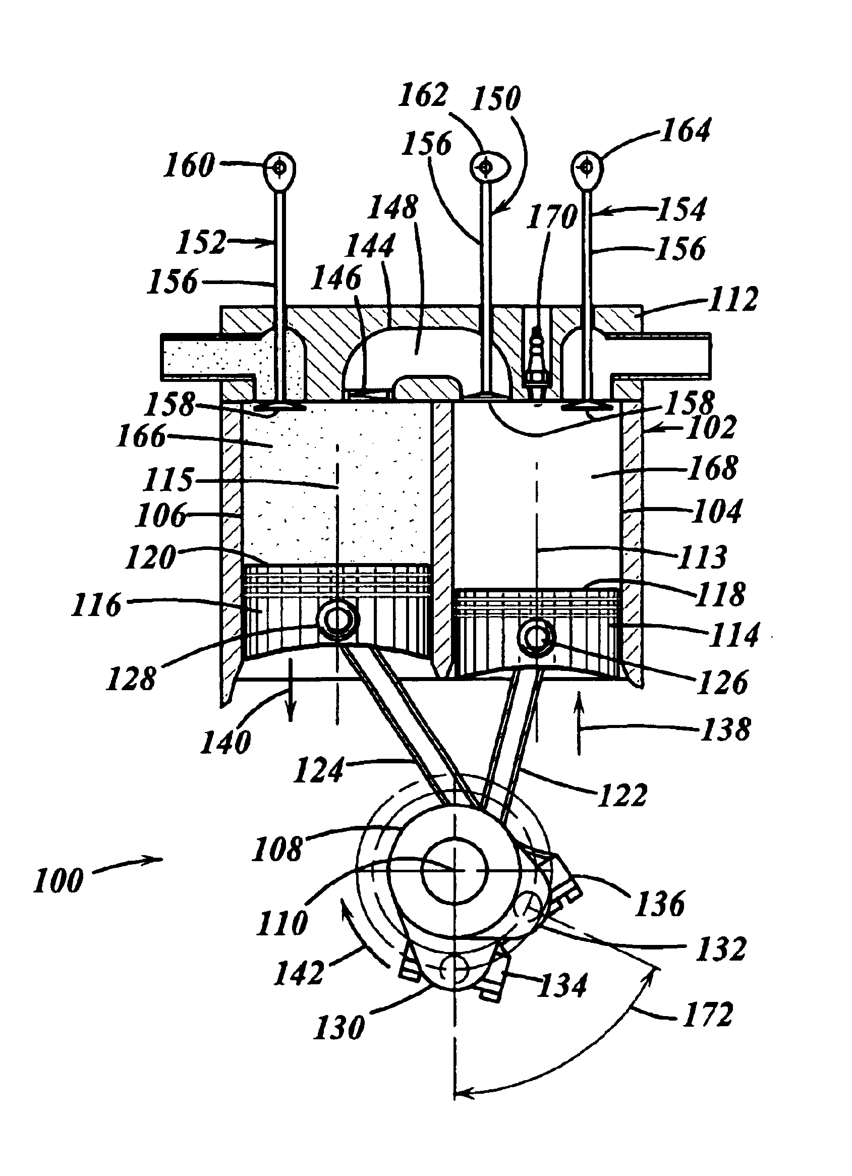
[0018]These and other advantages are accomplished in an exemplary embodiment of the invention by providing an engine having a crankshaft, rotating about a crankshaft axis of the engine. An expansion piston is slidably received within an expansion cylinder and operatively connected to the crankshaft such that the expansion piston reciprocates through an expansion stroke and an exhaust stroke of a four stroke cycle during a single rotation of the crankshaft. A compression piston is slidably received within a compression cylinder and operatively connected to the crankshaft such that the compression piston reciprocates through an intake stroke and a compression stroke of the same four stroke cycle during the same rotation of the crankshaft. A ratio of cylinder volumes from BDC to TDC for either one of the expansion cylinder and compression cylinder is substantially 20 to 1 or greater.
[0019]In an alternative embodiment of the invention the expansion piston and the compression piston of the engine have a TDC phasing of substantially 50°
crank angle or less.
[0020]In another alternative embodiment of the invention, an engine includes a crankshaft, rotating about a crankshaft axis of the engine. An expansion piston is slidably received within an expansion cylinder and operatively connected to the crankshaft such that the expansion piston reciprocates through an expansion stroke and an exhaust stroke of a four stroke cycle during a single rotation of the crankshaft. A compression piston is slidably received within a compression cylinder and operatively connected to the crankshaft such that the compression piston reciprocates through an intake stroke and a compression stroke of the same four stroke cycle during the same rotation of the crankshaft. A
crossover passage interconnects the compression and expansion cylinders. The crossover passage includes an
inlet valve and a crossover valve defining a pressure chamber therebetween. The crossover valve has a crossover valve duration of substantially 69° of
crank angle or less.
[0021]In still another embodiment of the invention an engine includes a crankshaft, rotating about a crankshaft axis of the engine. An expansion piston is slidably received within an expansion cylinder and operatively connected to the crankshaft such that the expansion piston reciprocates through an expansion stroke and an exhaust stroke of a four stroke cycle during a single rotation of the crankshaft. A compression piston is slidably received within a compression cylinder and operatively connected to the crankshaft such that the compression piston reciprocates through an intake stroke and a compression stroke of the same four stroke cycle during the same rotation of the crankshaft. A crossover passage interconnects the compression and expansion cylinders. The crossover passage includes an
inlet valve and a crossover valve defining a pressure chamber therebetween. The crossover valve remains open during at least a portion of a combustion event in the expansion cylinder.
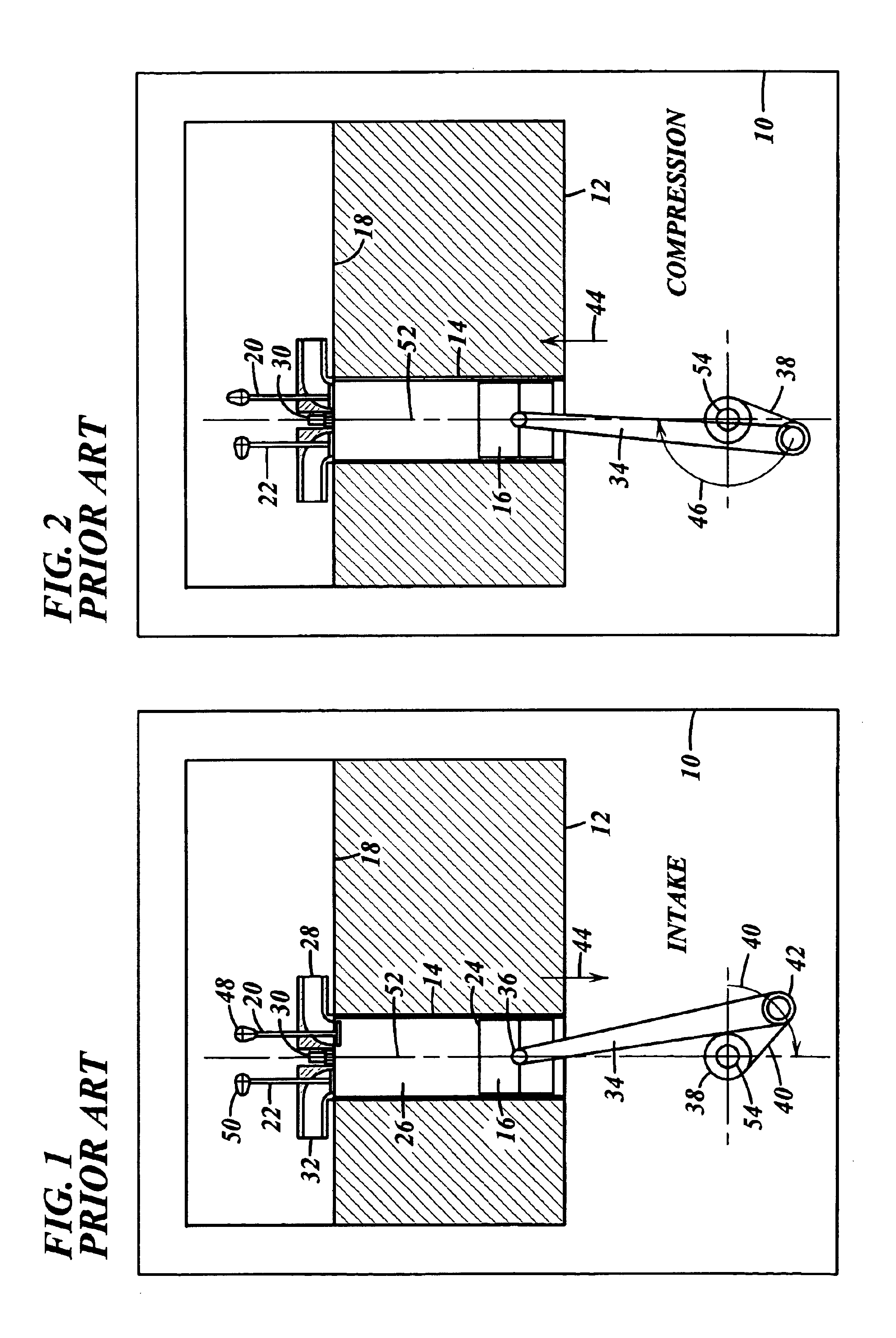
[0023]FIG. 2 is a
schematic diagram of the prior art engine of FIG. 1 during the compression stroke;
[0024]FIG. 3 is a
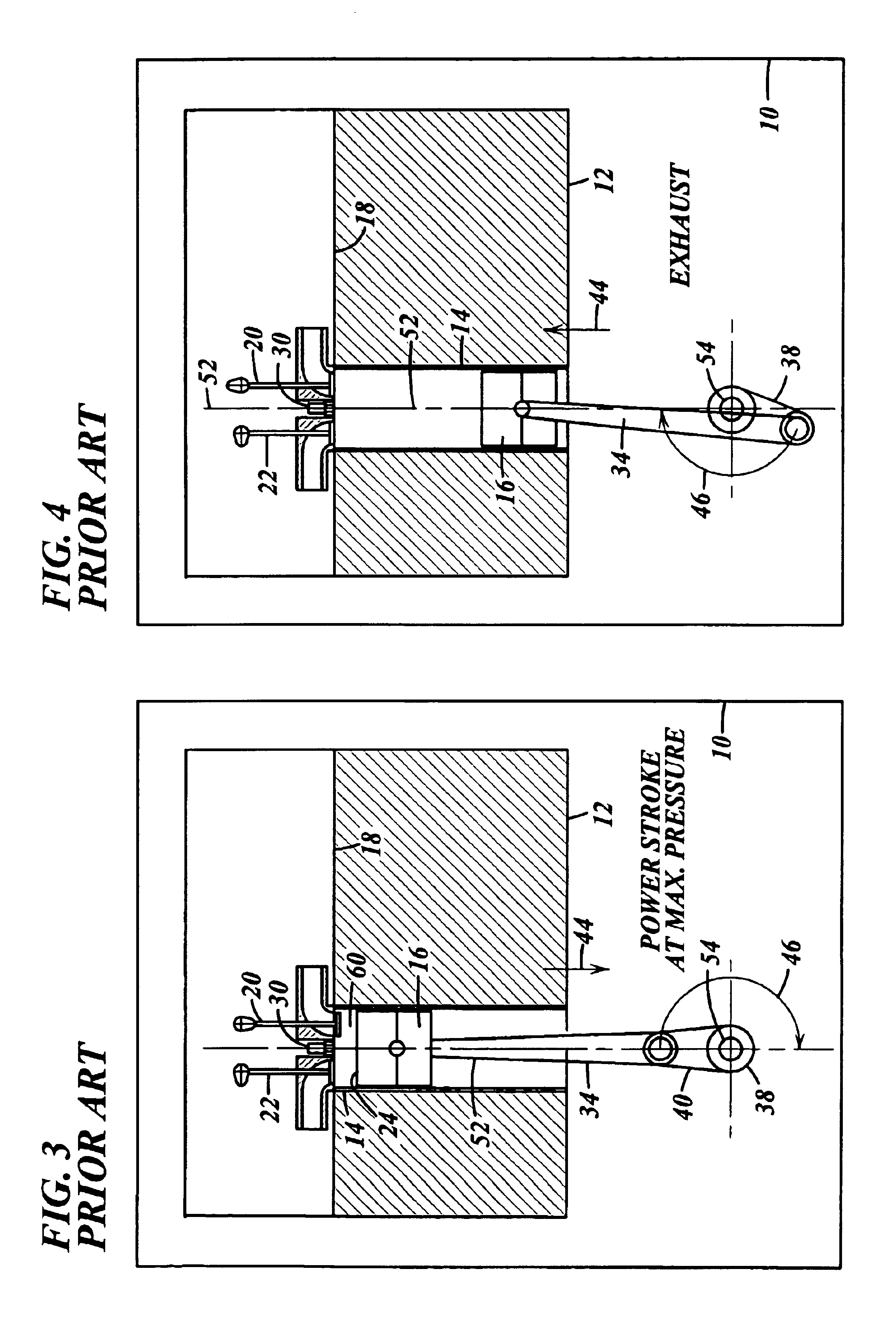
schematic diagram of the prior art engine of FIG. 1 during the expansion stroke;
[0025]FIG. 4 is a schematic diagram of the prior art engine of FIG. 1 during the exhaust stroke;
[0027]FIG. 6 is a schematic diagram of an exemplary embodiment of a split-cycle four stroke internal combustion engine in accordance with the present invention during the intake stroke;
[0028]FIG. 7 is a schematic diagram of the split-cycle engine of FIG. 6 during partial compression of the compression stroke;
[0029]FIG. 8 is a schematic diagram of the split-cycle engine of FIG. 6 during full compression of the compression stroke;
[0030]FIG. 9 is a schematic diagram of the split-cycle engine of FIG. 6 during the start of the combustion event;
[0031]FIG. 10 is a schematic diagram of the split-cycle engine of FIG. 6 during the expansion stroke;
[0032]FIG. 11 is a schematic diagram of the split-cycle engine of FIG. 6 during the exhaust stroke;
[0033]FIG. 12A is a schematic diagram of a GT-Power
graphical user interface for a conventional engine computer model used in a comparative Computerized Study;
[0034]FIG. 12B is the item definitions of the conventional engine of FIG. 12A;
The following glossary of acronyms and definitions of terms used herein is provided for reference:
[0023]FIG. 2 is a schematic diagram of the prior art engine of FIG. 1 during the compression stroke;
[0035]FIG. 13 is a typical Wiebe heat release curve;
[0036]FIG. 14 is a graph of performance parameters of the conventional engine of FIG. 12A;
[0037]FIG. 15A is a schematic diagram of a GT-Power
graphical user interface for a split-cycle engine computer model in accordance with the present invention and used in the Computerized Study;
The following glossary of acronyms and definitions of terms used herein is provided for reference:
[0039]FIG. 16 is a schematic representation of an MSC.ADAMS® model diagram of the
split cycle engine of FIG. 15A;
[0040]FIG. 17 is a graph of the compression and expansion piston positions and valve events for the split-cycle engine of FIG. 15A;
[0041]FIG. 18 is a graph of some of the initial performance parameters of the split-cycle engine of FIG. 15A;
[0042]FIG. 19 is a log-log
pressure volume diagram for a conventional engine;
[0043]FIG. 20 is a
pressure volume diagram for the power cylinder of a split-cycle engine in accordance with the present invention;
[0044]FIG. 21 is a comparison graph of indicated thermal efficiencies of a conventional engine and various split-cycle engines in accordance with the present invention;
[0045]FIG. 22 is a CFD predicted diagram of the
flame front position between the crossover valve and expansion piston for a 35% burn overlap case;
[0046]FIG. 23 is a CFD predicted diagram of the
flame front position between the crossover valve and expansion piston for a 5% burn overlap case;
[0047]FIG. 24 is a CFD predicted graph of
NOx emissions for a conventional engine, a split-cycle engine 5% burn overlap case and a split-cycle engine 35% burn overlap case;
[0048]FIG. 25 is a graph of the expansion piston thrust load for the split-cycle engine;
[0052]FIG. 29 is a graph of indicated power and thermal efficiency vs. crossover valve duration for a split cycle engine in accordance with the present invention.
[0053]The Scuderi Group, LLC commissioned the Southwest Research Institute® (SwRI®) of San Antonio, Tex. to perform a Computerized Study. The Computerized Study involved constructing a computerized model that represented various embodiments of a split-cycle engine, which was compared to a computerized model of a conventional four stroke internal combustion engine having the same trapped
mass per cycle. The Study's final report (SwRI® Project No. 03.05932, dated Jun. 24, 2003, titled “Evaluation Of Split-Cycle Four-
Stroke Engine Concept”) is herein incorporated by reference in its entirety. The Computerized Study resulted in the present invention described herein through exemplary embodiments pertaining to a split-cycle engine.
[0023]FIG. 2 is a schematic diagram of the prior art engine of FIG. 1 during the compression stroke;
The following glossary of acronyms and definitions of terms used herein is provided for reference:
[0054]Air / fuel Ratio: proportion of air to fuel in the intake charge
[0076]Indicated
Mean Effective Pressure (IMEP): the integration of the area inside the P-dV curve, which also equals the indicated engine torque divided by displacement volume. In fact, all indicated torque and power values are derivatives of this parameter. This value also represents the
constant pressure level through the expansion stroke that would provide the same engine output as the actual
pressure curve. Can be specified as net indicated (NIMEP) or gross indicated (GIMEP) although when not fully specified, NIMEP is assumed.
[0060]
Brake Torque: the torque output at the engine output shaft.
[0058]
Brake Thermal Efficiency (BTE): the prefix “
brake”: having to do with parameters derived from measured torque at the engine output shaft. This is the performance parameter taken after the losses due to friction. Accordingly BTE=ITE−friction.
[0059]Burn Overlap: the percentage of the total combustion event (i.e. from the 0% point to the 100% point of combustion) that is completed by the time of crossover valve closing.
[0060]
Brake Torque: the torque output at the engine output shaft.
[0061]
Crank Angle (CA): the
angle of rotation of the crankshaft throw, typically referred to its position when aligned with the cylinder bore.
[0062]Computational Fluid Dynamics (CFD): a way of solving complex fluid flow problems by breaking the flow regime up into a large number of tiny elements which can then be solved to determine the flow characteristics, the
heat transfer and other characteristics relating to the flow solution.

