Fuel cell stack and a method of operating the same

a fuel cell and stack technology, applied in the direction of fuel cells, cell components, electrochemical generators, etc., can solve the problems of large difference between the temperature of the fuel cell stack and the external air temperature, shortage of reaction gases dew condensation in the end cells, so as to achieve the effect of preventing the temperature drop of the fuel cell, simple operation process and simple structur

Inactive Publication Date: 2005-10-11
HONDA MOTOR CO LTD
View PDF7 Cites 15 Cited by
  • Summary
  • Abstract
  • Description
  • Claims
  • Application Information

AI Technical Summary

Benefits of technology

[0012]An general object of the present invention is to provide a fuel cell stack and a method of operating the fuel cell stack in which the temperature drop of the fuel cells is effectivel...

Problems solved by technology

Further, dew condensation may occur in the end cells.
In particular, when the fuel cell stack is operated at a temperature below the freezing point, the difference between the temperature in the fuel cell stack and the external air temperature is large.
As a result, a shortage of reaction gases may occur in the end cells.
The shortage of the reaction gases gives rise to a voltage drop in the end cells.
T...

Method used


Image

  • Fuel cell stack and a method of operating the same
  • Fuel cell stack and a method of operating the same
  • Fuel cell stack and a method of operating the same

Examples


first embodiment

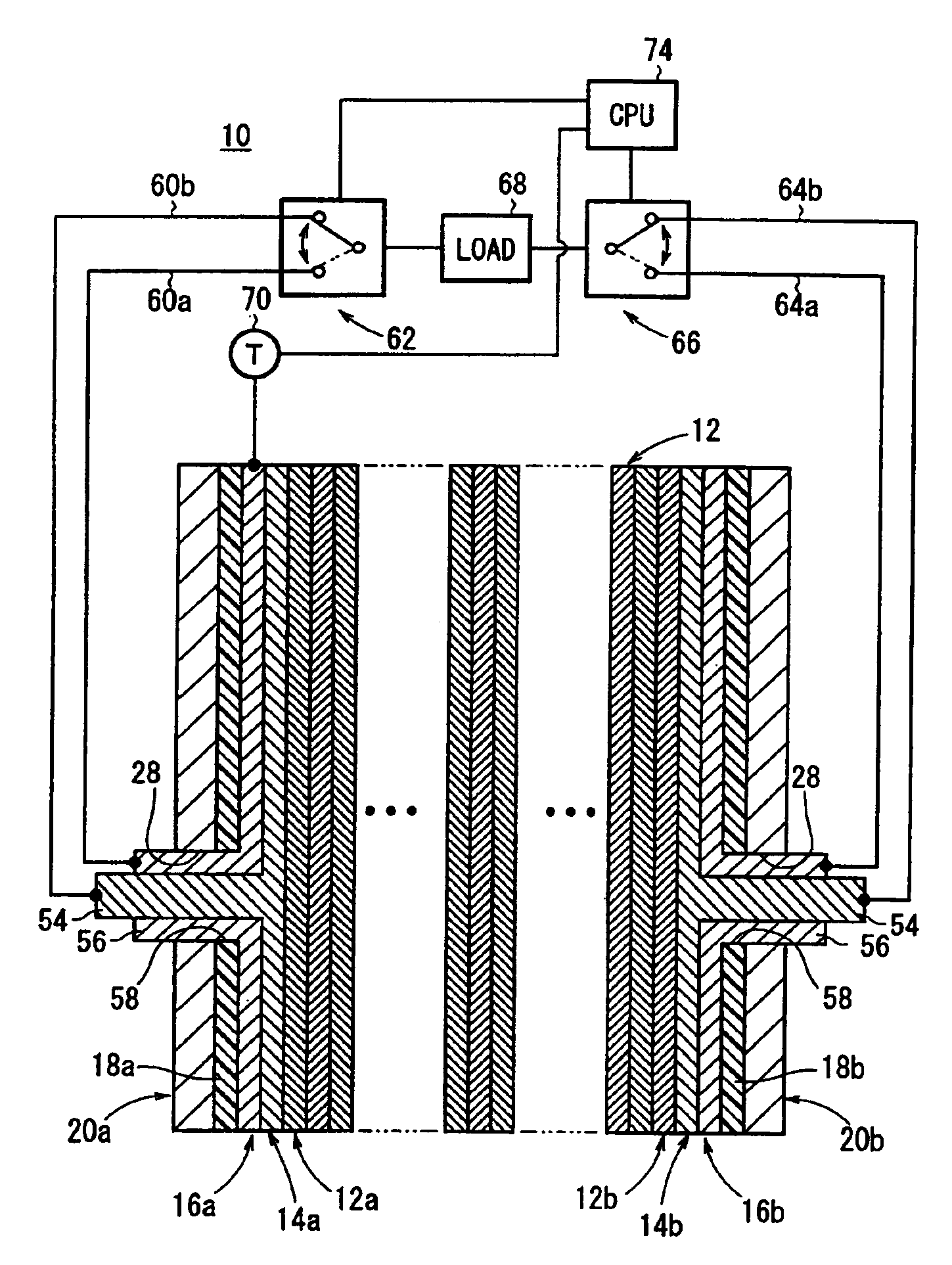
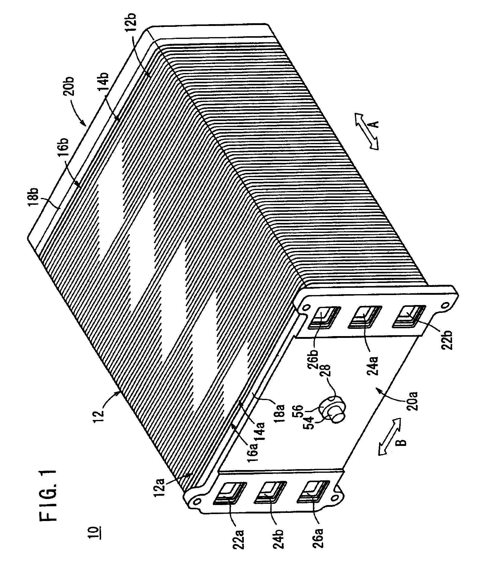
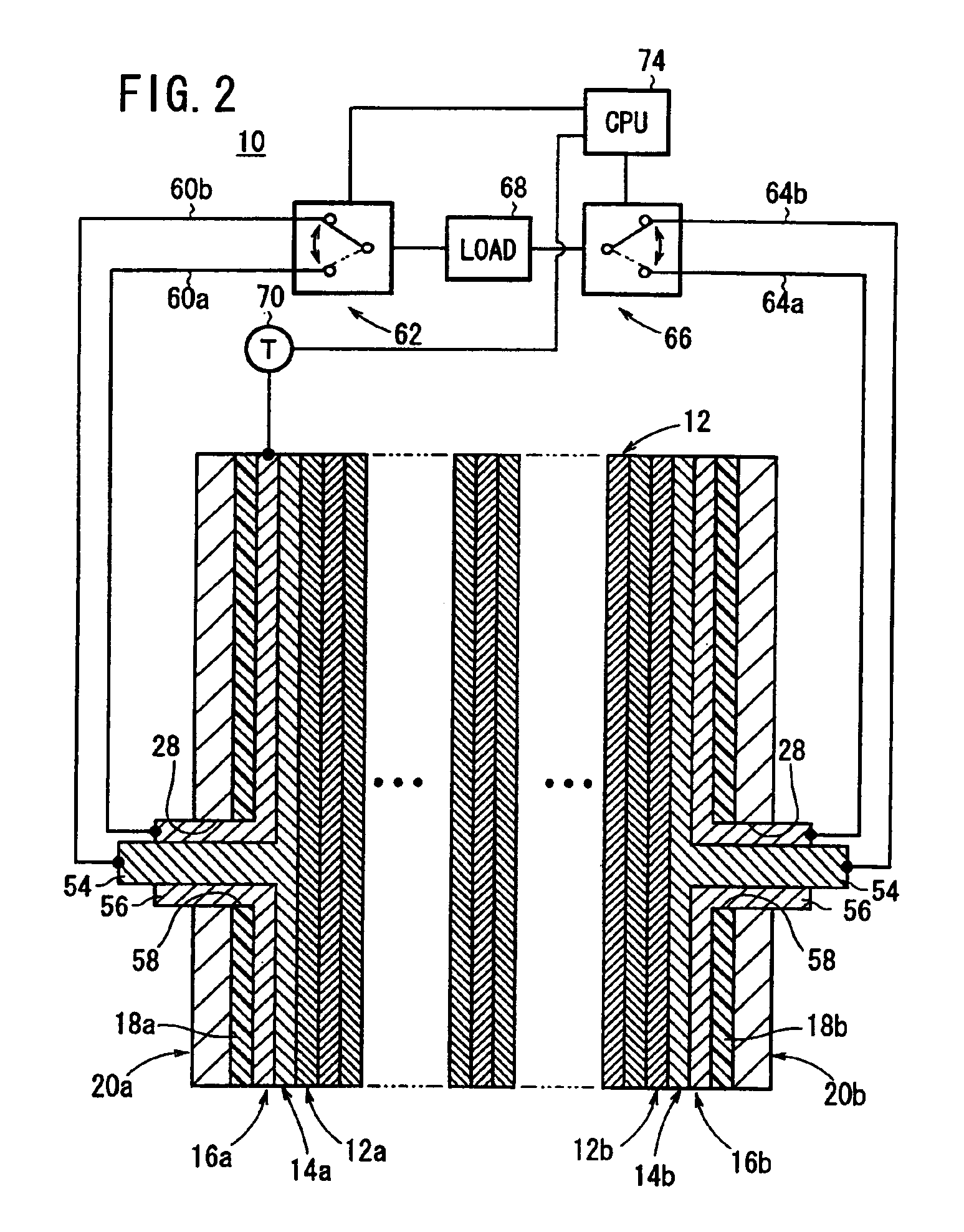
[0030]FIG. 1 is a schematic perspective view showing a fuel cell stack 10 according to the present invention, and FIG. 2 is a view showing a circuit for delivering electricity from the fuel cell stack 10. FIG. 3 is an exploded perspective view showing main components of the fuel cell stack 10.

[0031]The fuel cell stack 10 includes a plurality of fuel cells 12 stacked in a direction indicated by an arrow A. End cells (outermost fuel cells) 12a, 12b are disposed at opposite ends in the stacking direction of the fuel cells 12. A cathode current collector 14a and an anode current collector 14b are stacked on the end cells 12a, 12b. Heating members 16a, 16b are stacked on the outside of the cathode current collector 14a and the anode current collector 14b, respectively. Insulating plates 18a, 18b are stacked on the outside of the heating members 16a, 16b, respectively. Further, end plates 20a, 20b are stacked on the outside of the insulating plates 18a, 18b, respectively. The fuel cells 1...

third embodiment

[0060]FIG. 7 is a schematic view showing a fuel cell stack 90 according to the present invention.

[0061]In the third embodiment, first heating members 92a, 92b, second heating members 94a, 94b, and third heating members 96a, 96b are stacked together on the outside of the current collectors 82a, 82b, respectively. The first heating members 92a, 92b, the second heating members 94a, 94b, and the third heating members 96a, 96b include power outputting terminals 98a, 98b, 100a, 100b, 102a, 102b, respectively. Each of the power outputting terminals 98a, 98b, 100a, 100b, 102a, 102b has a planar shape and a bent portion.

[0062]As shown in FIG. 8, the power outputting terminal 86a, 86b, 98a, 98b, 100a, 100b, 102a, 102b are connected to first and second switches 112, 114 through lead wires 104a, 104b, 106a, 106b, 108a, 108b, 110a, 110b, respectively. A load 68 is connected to power outputting lines 116a, 116b.

[0063]The first and second switches 112, 114 have four switching positions, i.e., a f...


PUM


Abstract

A plurality of fuel cells are stacked together. Current collectors are stacked on the fuel cells at opposite ends in a stacking direction of said fuel cells, and heating members are stacked on the outside of said current collectors. In a normal operating condition, electricity is delivered through the current collectors. When the temperature of end cells is lowered, a switching operation is performed to stop delivering electricity through the current collectors and start delivering electricity through the heating members.

Description

BACKGROUND OF THE INVENTION[0001]1. Field of the Invention[0002]The present invention relates to a fuel cell stack and a method of operating the fuel cell stack. The fuel cell stack comprises a plurality of fuel cells stacked together. Each of the fuel cells includes a pair of separators and an electrolyte electrode assembly interposed between the separators. The fuel cell stack further comprises an anode current collector and a cathode current collector stacked on outermost fuel cells at opposite ends in a stacking direction of the fuel cells.[0003]2. Description of the Related Art[0004]In recent years, various types of fuel cells such as a polymer electrolyte fuel cell (PEFC) have been developed. The polymer electrolyte fuel cell employs a membrane electrode assembly (MEA) which comprises two electrodes (anode and cathode) and an electrolyte membrane interposed between the electrodes. The electrolyte membrane is a polymer ion exchange membrane (proton exchange membrane). Each of t...

Claims


Application Information

Patent Timeline
IPC IPC(8): H01M8/24H01M8/04H01M8/10
CPCH01M8/0228H01M8/0247H01M8/0267H01M8/04007H01M8/04074H01M8/04268H01M8/04365H01M8/04664H01M8/04671H01M8/04731H01M8/241H01M8/04037Y02E60/50H01M8/2483
Inventor HAYASHI, KATSUMIKATO, HIDEO
Owner HONDA MOTOR CO LTD
Why Eureka
Try Eureka