Method for encoding and decoding video information, a motion compensated video encoder and a corresponding decoder

a technology of video information and encoder, which is applied in the field of encoding and decoding video information, a motion compensated video encoder and a corresponding decoder, can solve the problems of inefficiency in transmitting a separate motion vector, operation usually produces some degradation, and the amount of data required to represent the video sequence is large, etc., to achieve good performance in terms of transmission bandwidth and image quality, and computationally fairly simple, flexible and versatile

Inactive Publication Date: 2005-10-11
NOKIA TECHNOLOGLES OY
View PDF5 Cites 5 Cited by
  • Summary
  • Abstract
  • Description
  • Claims
  • Application Information

AI Technical Summary

Benefits of technology

[0028]An object of the present invention is to provide a method that provides a flexible and versatile motion coefficient prediction for encoding/decoding video information using motion compensation. A further object of the invention is to provide a motion compensated method for coding/decoding video information that ...

Problems solved by technology

Because of the large number of pixels in a video frame and the large number of video frames even in a typical video sequence, the amount of data required to represent the video sequence quickly becomes large.
Due to the very large number of pixels in a frame it is not efficient to transmit a separate motion vector for each pixel to the decoder.
Because of the error introduced by quantization, this operation usually produces some degradation in the prediction error frame En(x,y).
The quadratic motion model provides good prediction performance, but it is less popular in coding than the affine model since it uses more motion coefficients, while the prediction performance is not substantially better than, for example, that of the affine motion model.
Furthermore, it is computationally more cost...

Method used


Image

  • Method for encoding and decoding video information, a motion compensated video encoder and a corresponding decoder
  • Method for encoding and decoding video information, a motion compensated video encoder and a corresponding decoder
  • Method for encoding and decoding video information, a motion compensated video encoder and a corresponding decoder

Examples


Embodiment Construction

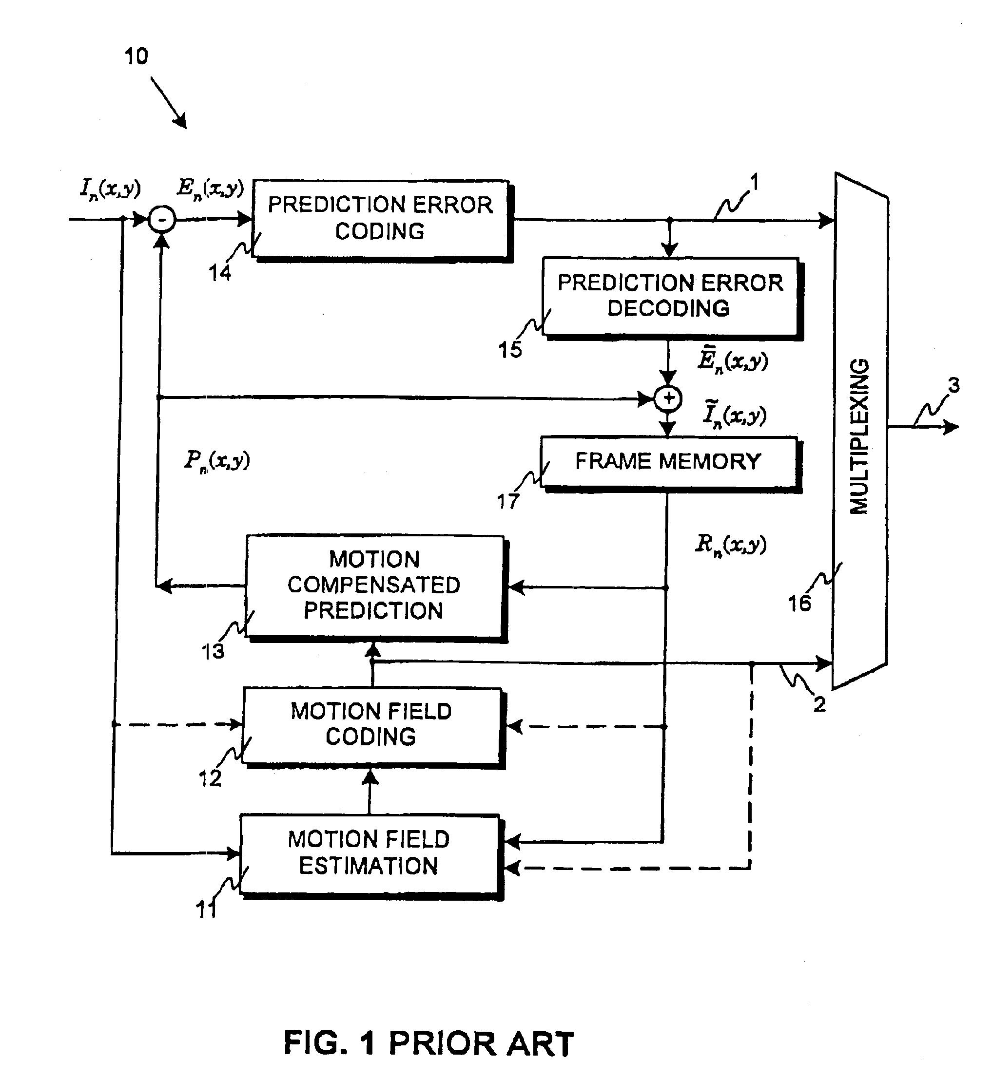
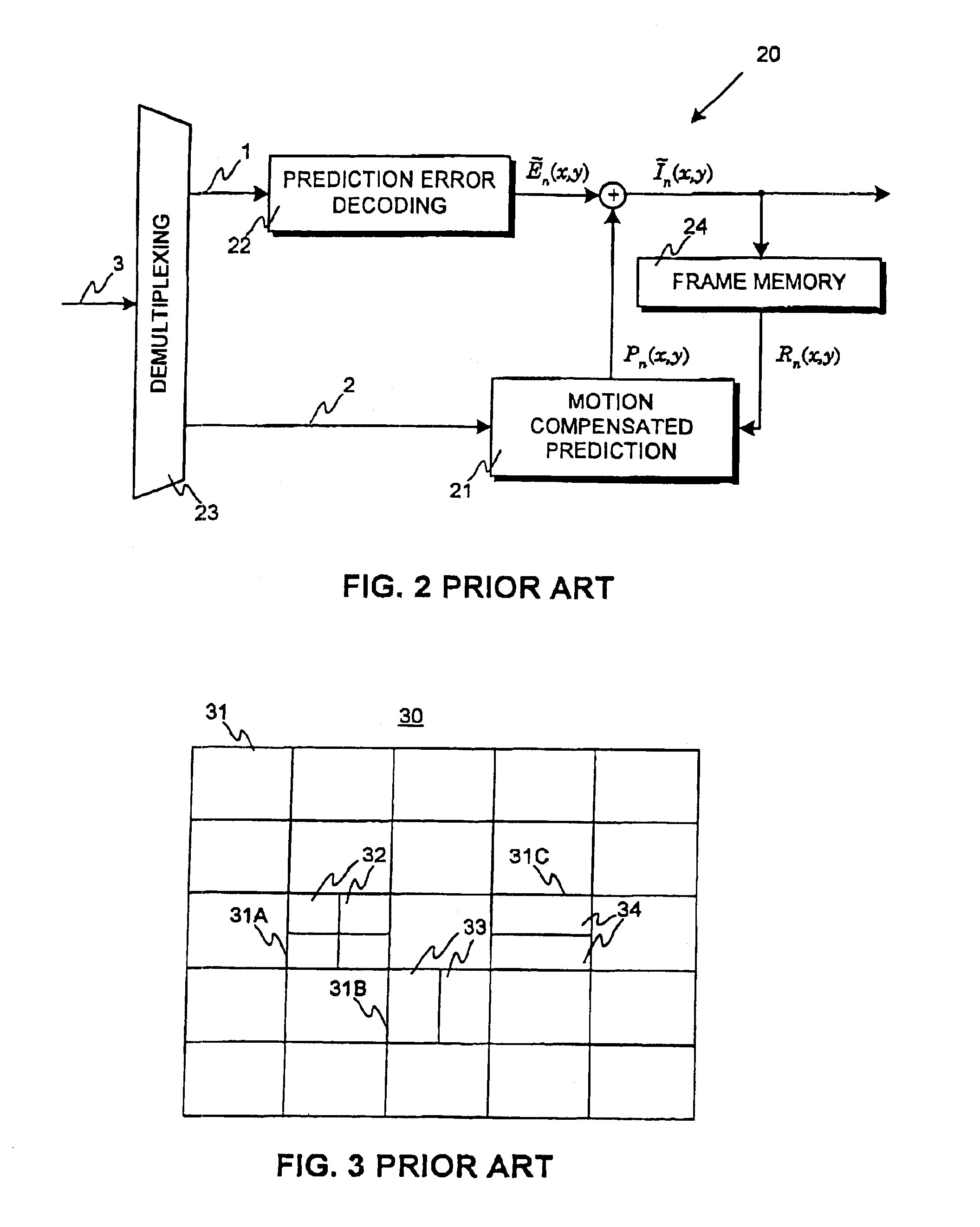
[0073]FIGS. 1-3 are discussed in detail in the description of motion compensated video encoding and decoding according to prior art.

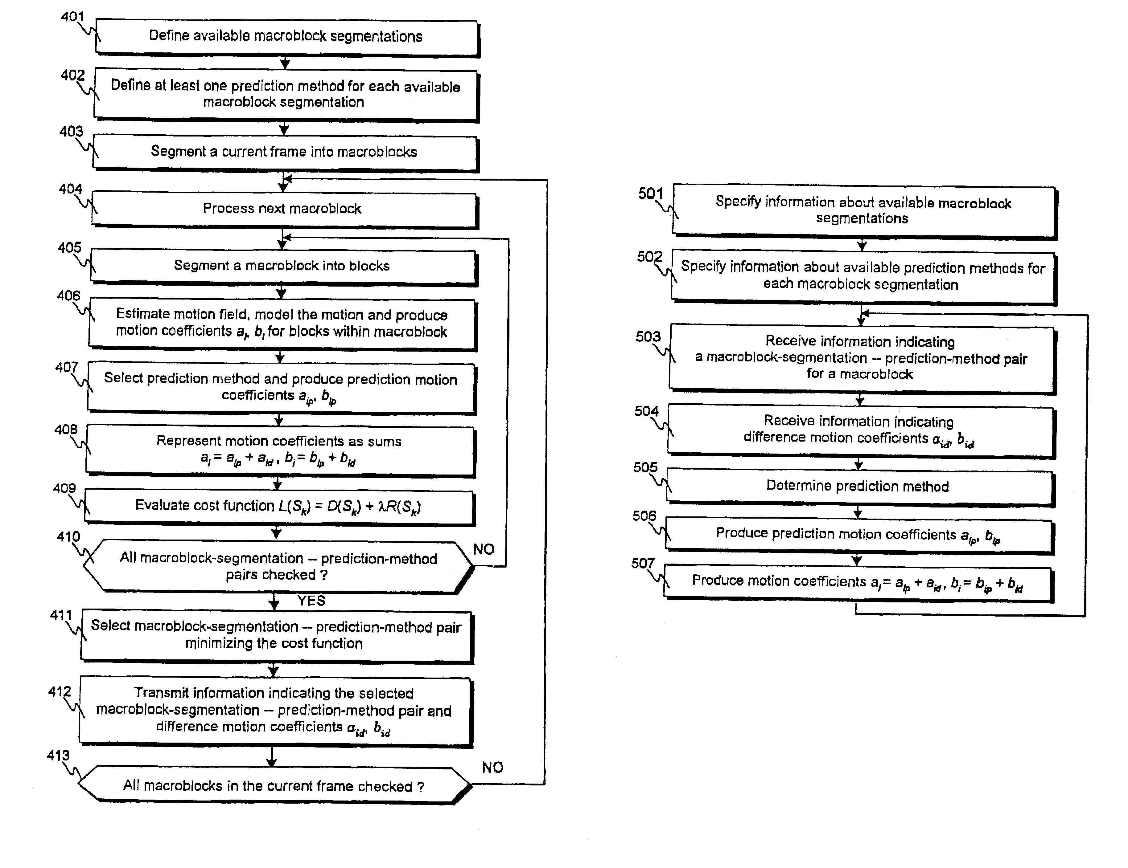
[0074]FIG. 4 presents a flowchart of a method for encoding video information according to the invention. Only features related to motion encoding are presented in FIG. 4, it does not present, for example, the formation or coding of the prediction error frame. Typically these features are included in encoding methods according to the invention and, of course, may be implemented in any appropriate manner.

[0075]In step 401 the available macroblock segmentations are defined The available macroblock segmentations can comprise, for example, such macroblock segmentations as presented in FIG. 3. In step 402 at least one prediction method for predicting motion coefficients is defined for each available macroblock segmentation, resulting in a certain number of available macroblock-segmentation—prediction-method pairs. Typically, for certain macroblock segmentatio...


PUM


Abstract

A method for encoding video information is presented, where a piece of current video information is segmented into macroblocks and a certain number of available macroblock segmentations for segmenting a macroblock into blocks is defined. Furthermore, for each available macroblock segmentation at least one available prediction method is defined, each of which prediction methods produces prediction motion coefficients for blocks within said macroblock, resulting in a certain finite number of available macroblock-segmentation—prediction-method pairs. For a macroblock one of the available macroblock-segmentation—prediction-method pairs is selected, and thereafter the macroblock is segmented into blocks and prediction motion coefficients for the blocks within said macroblock are produced using the selected macroblock-segmentation—prediction-method pair. A corresponding decoding method, an encoder and a decoder are also presented.

Description

[0001]This application is a continuation of application Ser. No. 09 / 566,020, filed May 8, 2000, now U.S. Pat. No. 6,711,211.[0002]The present invention relates to video coding. In particular, it relates to compression of video information using motion compensated prediction.BACKGROUND OF THE INVENTION[0003]A video sequence typically consists of a large number video frames, which are formed of a large number of pixels each of which is represented by a set of digital bits. Because of the large number of pixels in a video frame and the large number of video frames even in a typical video sequence, the amount of data required to represent the video sequence quickly becomes large. For instance, a video frame may include an array of 640 by 480 pixels, each pixel having an RGB (red, green, blue) color representation of eight bits per color component, totaling 7,372,800 bits per frame. Another example is a QCIF (quarter common intermediate format) video frame including 176×144 pixels. QCIF ...

Claims


Application Information

Patent Timeline
IPC IPC(8): G06T9/00H04N7/36H04N7/26H03M7/36H04N19/176H04N19/51
CPCH04N19/56H04N19/503H04N19/51H04N19/19H04N19/20H04N19/537H04N19/567H04N19/517H04N19/176
Inventor LAINEMA, JANI
Owner NOKIA TECHNOLOGLES OY
Why Eureka
Try Eureka