

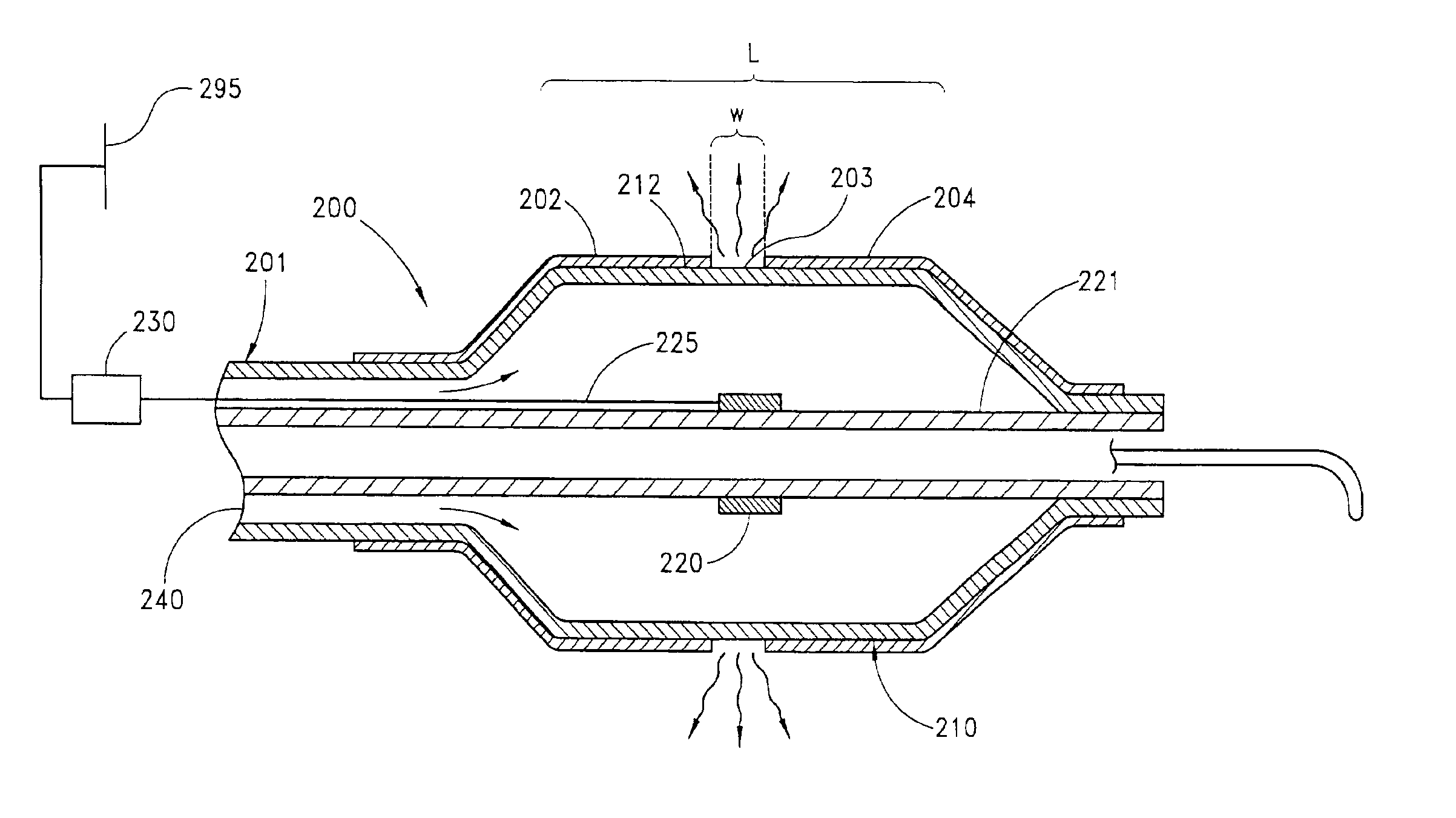
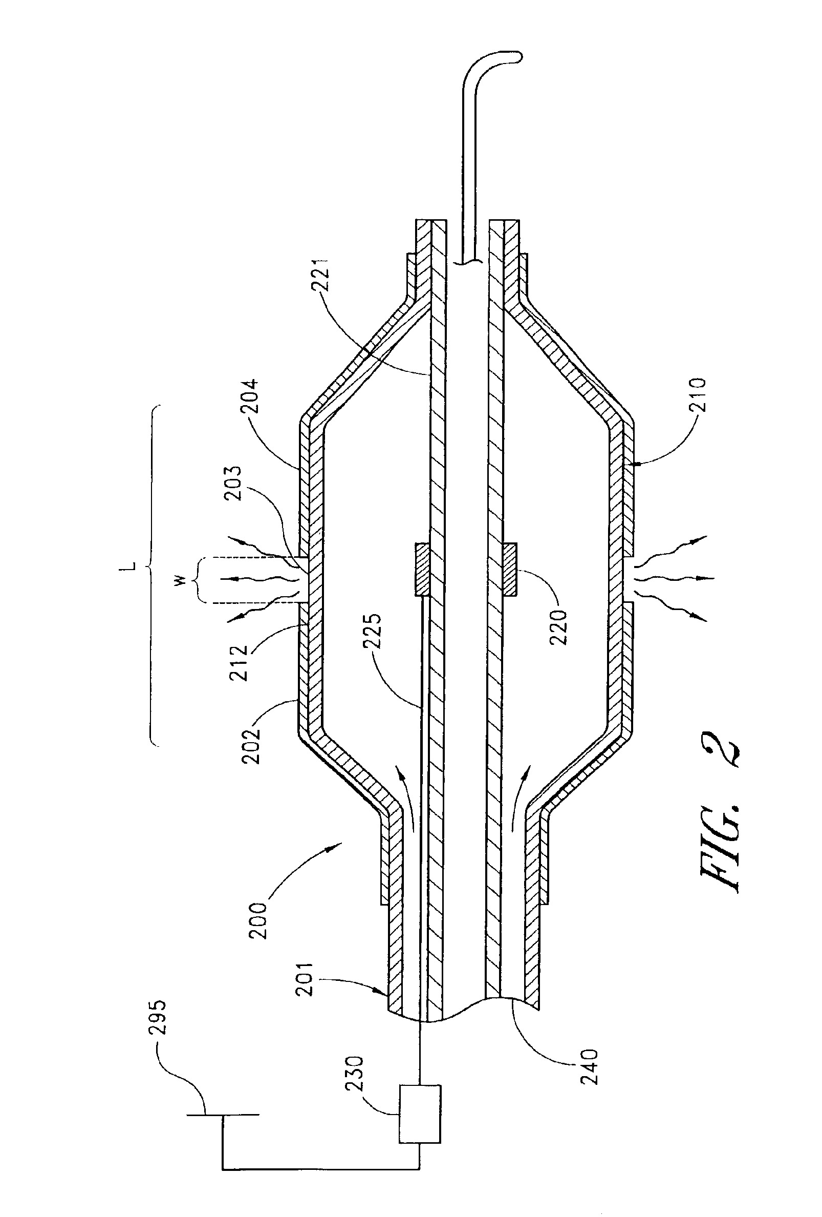
Circumferential ablation device assembly and methods of use and manufacture providing an ablative circumferential band along an expandable member
a technology of circumferential ablation and expandable member, which is applied in the direction of catheters, food packaging, therapy, etc., can solve the problems of proarrhythmia and long-term ineffectiveness, general belief of entirely effective, and procedure may be substantially effectiv
- Summary
- Abstract
- Description
- Claims
- Application Information
AI Technical Summary
Benefits of technology
Problems solved by technology
Method used
Image

Examples
Embodiment Construction
[0115]Particular Definitions
[0116]Various terms are defined throughout this specification, and the meaning of any particular term is to be understood in the context of this entire document, in addition to the context of a particular description or use given in a specific circumstance as described hereunder. Such terms are to be understood as follows:
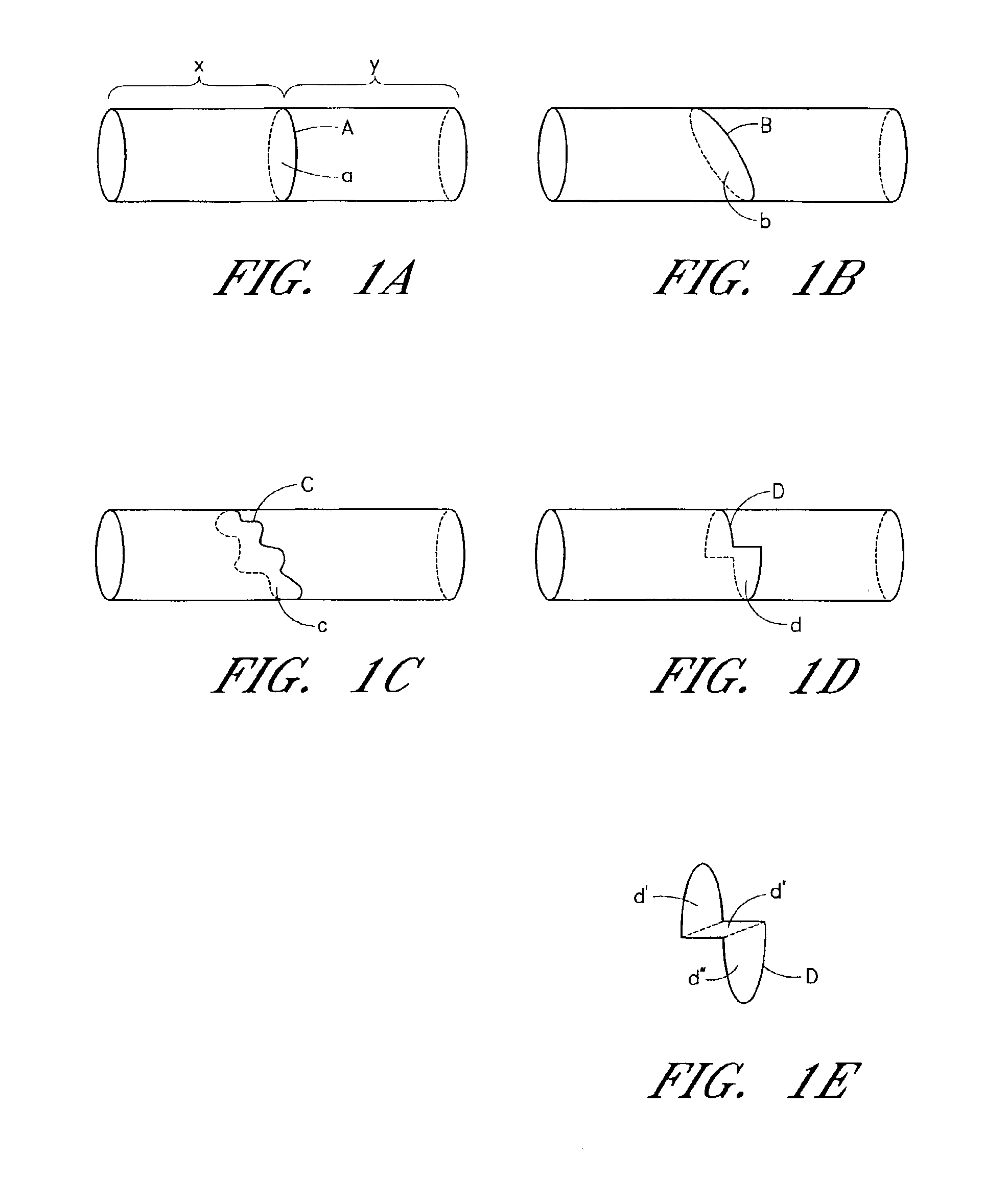
[0117]The terms “circumference” or “circumferential”, including derivatives thereof, are herein intended to mean a continuous path or line which forms an outer border or perimeter that surrounds and thereby defines an enclosed region of space. Such a continuous path starts at one location along the outer border or perimeter, and translates along the outer border or perimeter until it is completed at the original starting location to enclose the defined region of space. The related term “circumscribe,” including derivatives thereof, is herein intended to mean to enclose, surround, or encompass a defined region of space. Therefore, accordi...
PUM
| Property | Measurement | Unit |
|---|---|---|
| Permeability | aaaaa | aaaaa |
| Pore | aaaaa | aaaaa |
| aaaaa | aaaaa |
Abstract
Description
Claims
Application Information