Multilayer capacitor

a multi-layer capacitor and capacitor technology, applied in the field of multi-layer capacitors, can solve the problems of difficult voltage fluctuation control, higher-speed and larger current fluctuation, and increase the cost of production, so as to reduce the cost of production

Active Publication Date: 2005-10-18
TDK CORPARATION
View PDF7 Cites 20 Cited by
  • Summary
  • Abstract
  • Description
  • Claims
  • Application Information

AI Technical Summary

Benefits of technology

[0012]In view of the above-described circumstances, it is an object of the present invention to provide a multilayer capacitor easily realizing a higher capacity as well as reduced ESL, thereby achieving a higher effect as a power source of a CPU.
[0020]In addition, two kinds of the terminal electrodes are alternately arranged on the one face of the dielectric element of the multilayer capacitor, so that the terminal electrodes adjacent to each other are different in polarity. Therefore, as for the directions of currents flowing into the terminal electrodes, the directions in the adjacent terminal electrodes become reverse to each other, so that a magnetic flux canceling effect acts between the adjacent terminal electrodes to reduce ESL.
[0021]Consequently, in the multilayer capacitor having the structure of this mode, not only ESL is reduced but also no multilayer block not functioning as a capacitor exists in the dielectric element. This makes it possible to increase capacitance compared with that of a conventional multilayer capacitor. Therefore, according to this mode, it is possible to obtain a multilayer capacitor easily realizing a higher capacity as well as reduced ESL, and this multilayer capacitor has a higher effect as a power source of a CPU.
[0025]Therefore, since the second multilayer block having no readout portion led out to one face of the dielectric element on which the terminal electrodes exist is interposed between the first multilayer blocks, it is possible to surely provide a gap between two kinds of the terminal electrodes disposed on this one face. This makes it possible to more surely achieve the operation and effect of the above-described mode.
[0029]Therefore, when two kinds of the terminal electrodes exist both in plurality, two kinds of the terminal electrodes are disposed on the one face of the dielectric element with the terminal electrodes different in kind being adjacent to each other, so that two kinds of the terminal electrodes are both arranged in a zigzag pattern. In accordance therewith, the terminal electrodes with the same polarity exist in the zigzag pattern. Therefore, two kinds of the terminal electrodes are alternately arranged both in the zigzag pattern, so that the magnetic flux canceling effect acts more strongly between the terminal electrodes adjacent to each other. This further ensures the achievement of the operation and effect of reducing ESL brought about by the modes previously described.

Problems solved by technology

This has caused the occurrence of a higher-speed and larger current fluctuation in a power source for supplying power to the CPU, and it has become very difficult to control voltage fluctuation accompanying this current fluctuation within an allowable value range of this power source.
However, today's trend toward a still higher frequency of the operating frequency of the CPU has resulted in higher-speed and larger current fluctuation.
As a result, this equivalent series inductance gives a significant influence to the voltage fluctuation of the power source, so that it is not possible to respond to the future increase in processing speed of a CPU.
However, due to the existence of the plural multilayer blocks 122 that do not function as capacitors in the dielectric element 100, it is difficult for the multilayer capacitor 100 as structured above to have an increased capacity.

Method used


Image

  • Multilayer capacitor
  • Multilayer capacitor
  • Multilayer capacitor

Examples


Embodiment Construction

[0043]Hereinafter, a first embodiment of the multilayer capacitor according to the present invention will be described based on the drawings.

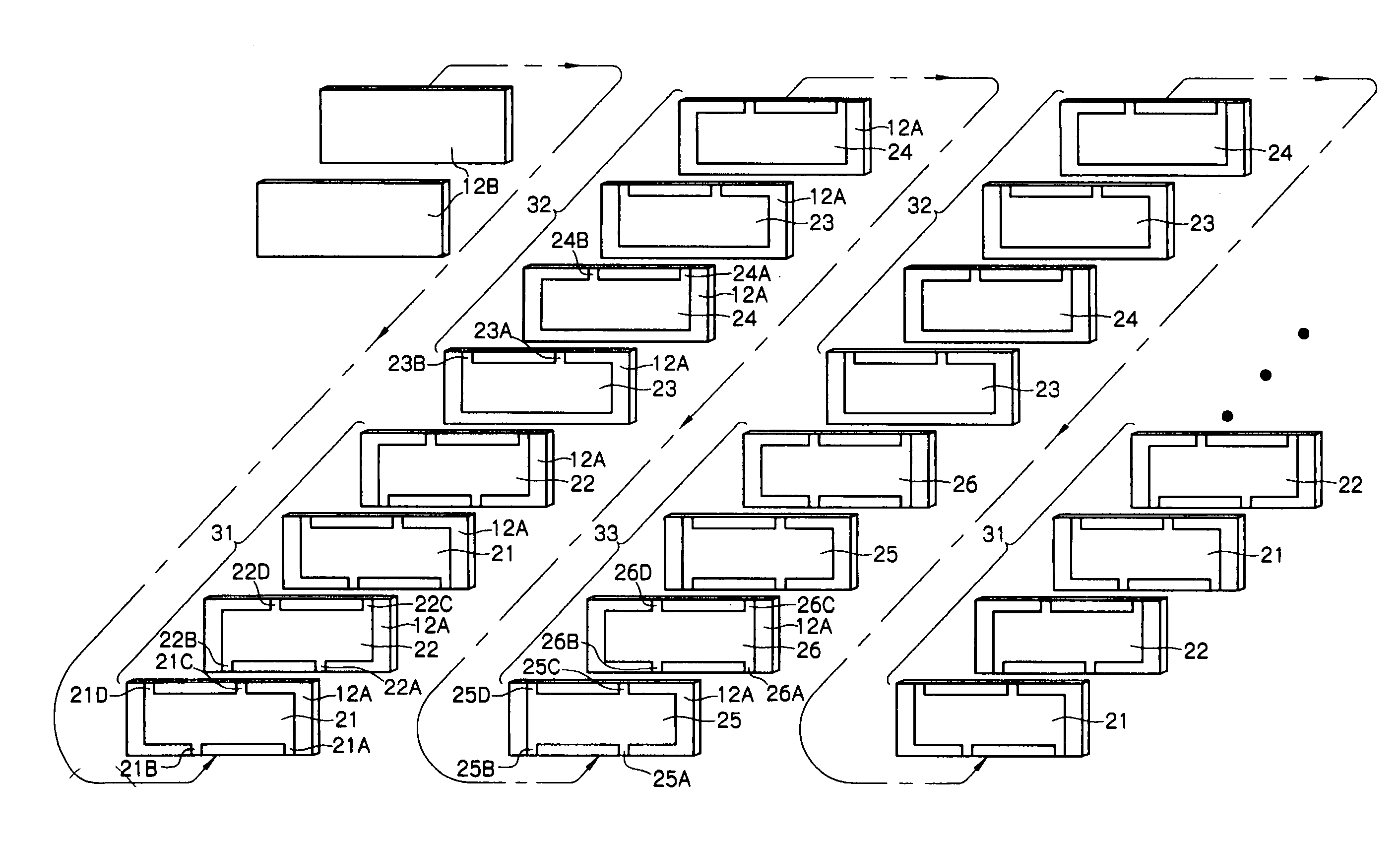
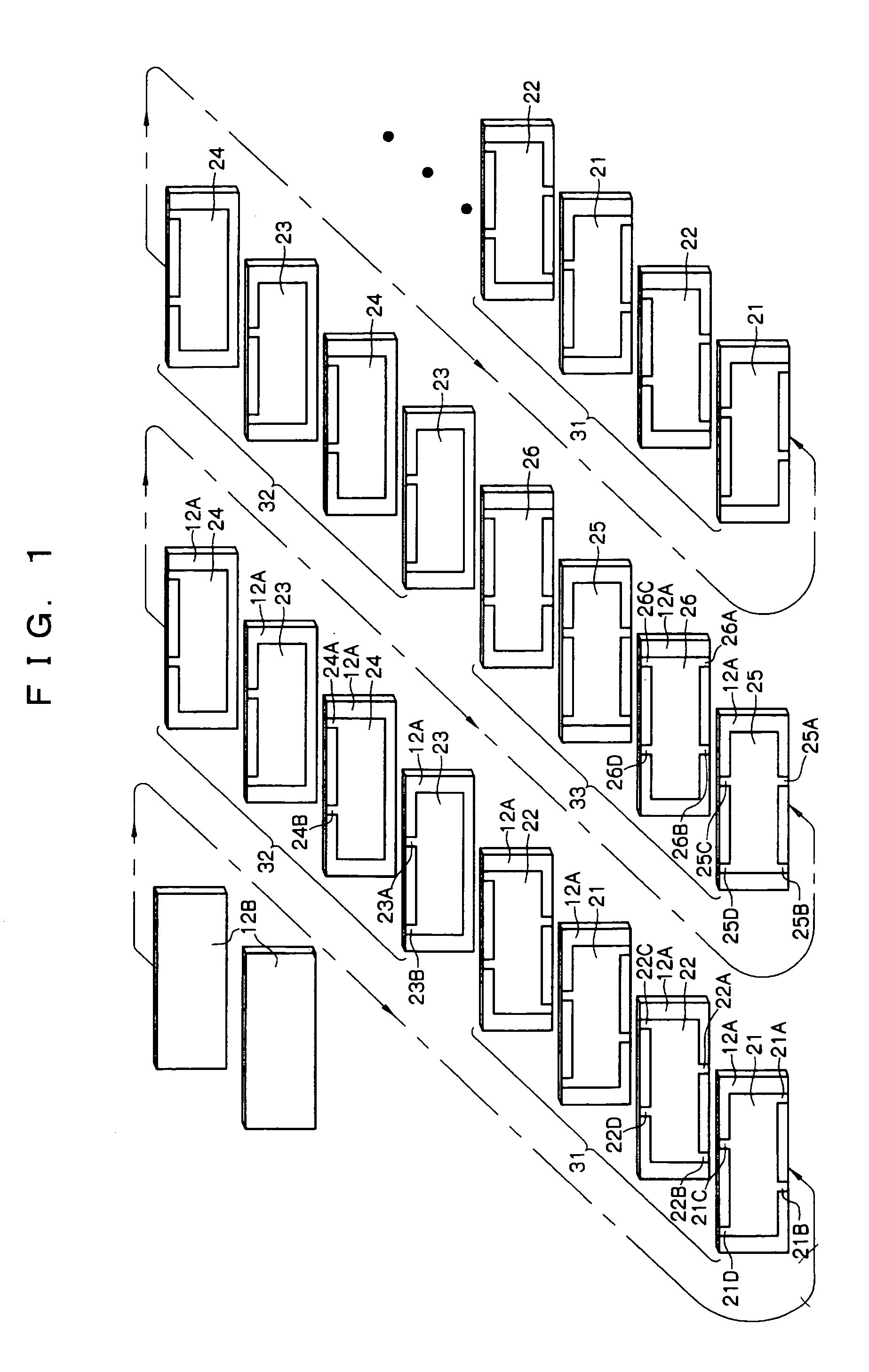
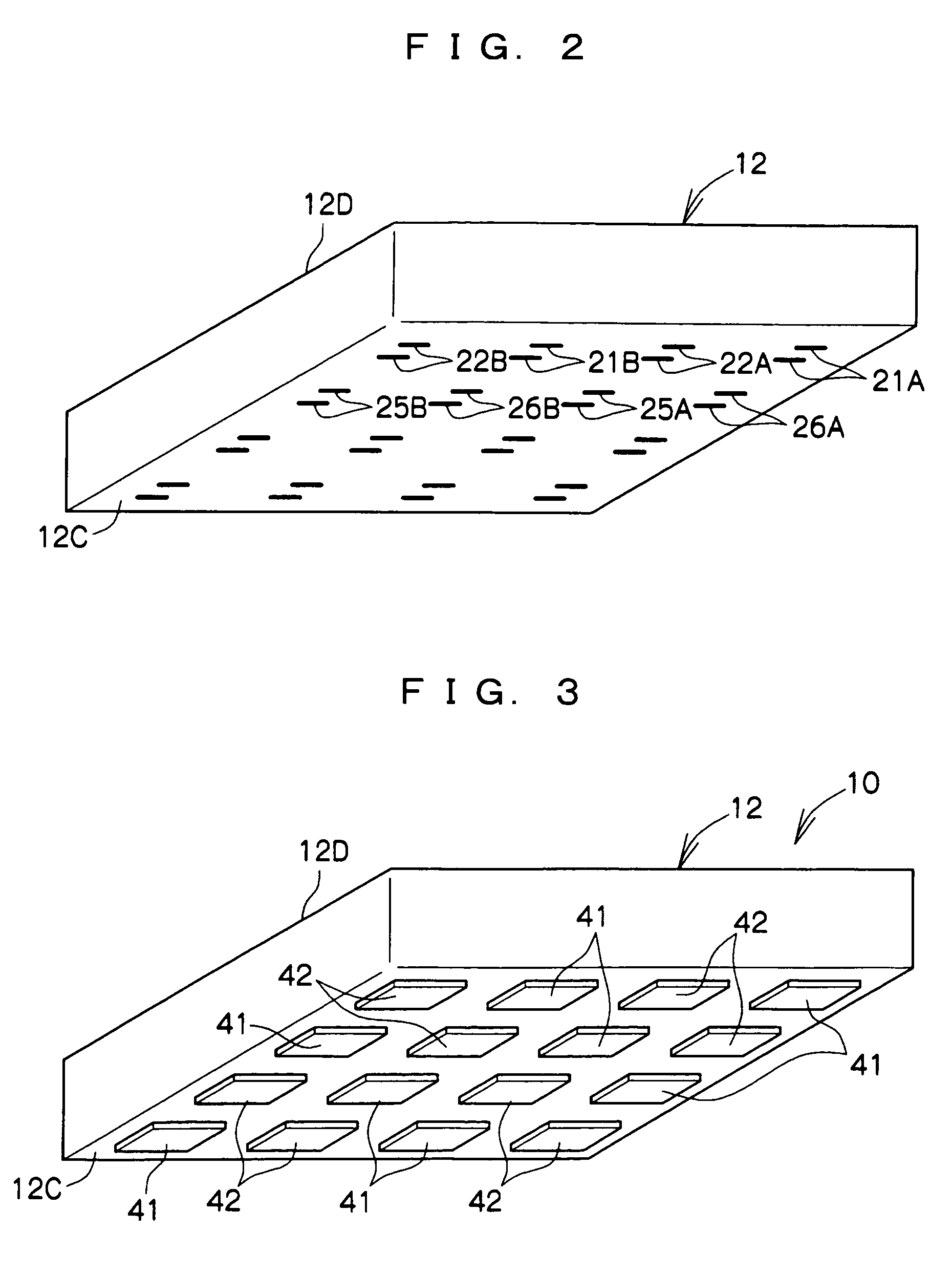
[0044]FIG. 1 to FIG. 7(B) show a multilayer ceramic capacitor (hereinafter, simply referred to as a multilayer capacitor) 10 being the multilayer capacitor according to this embodiment. As seen in these drawings, the multilayer capacitor 10 includes, as a major portion thereof, a dielectric element 12 being a sintered compact in a parallelepiped shape that is obtained by sintering a multilayer body formed of a stack of a plurality of ceramic green sheets which are dielectric sheets.

[0045]As shown in FIG. 1, ceramic layers 12B without any internal conductor are disposed as protective layers (two layers in the drawing) at a front end of the dielectric element 12, and a planar internal conductor 21 is disposed at a position in the dielectric element 12 at the back of the ceramic layers 12B. An internal conductor 22 similarly in a planar shape is d...


PUM

PropertyMeasurementUnit
dielectricaaaaaaaaaa
polarityaaaaaaaaaa
operating voltageaaaaaaaaaa

Abstract

A multilayer capacitor includes: a dielectric element; two kinds of terminal internal conductors and two kinds of connecting internal conductors both disposed in the dielectric element; two kinds of terminal electrodes; and two kinds of external electrodes, wherein: the terminal internal conductor of one kind has a first terminal-side leadout portion led out to one face of the dielectric element and a first external-side leadout portion led out to the other face, and the terminal internal conductor of the other kind has a second terminal-side leadout portion led out to the one face and a second external-side leadout portion led out to the other face; the connecting internal conductor of one kind has a third external-side leadout portion led out to the other face, and the connecting internal conductor of the other kind has a fourth external-side leadout portion led out to the other face; the terminal electrode of one kind is connected to the first terminal-side leadout portion, and the terminal electrode of the other kind is connected to the second terminal-side leadout portion; and the external electrode of one kind is connected to the first external-side leadout portion and the third external-side leadout portion, and the external electrode of the other kind is connected to the second external-side leadout portion and the fourth external-side leadout portion. Therefore, a multilayer capacitor easily realizing a higher capacity and reduced ESL is obtained.

Description

BACKGROUND OF THE INVENTION[0001]1. Field of the Invention[0002]The present invention relates to a multilayer capacitor that easily realizes a higher capacity as well as reduced ESL, and more particularly, to that suitable for use as a multilayer ceramic capacitor for achieving a high effect as a power source of a CPU.[0003]2. Description of the Related Art[0004]In recent years, due to an improved processing speed and a higher integration degree of a CPU (central processing unit) used for a data processor, its operating frequency is becoming higher and its current consumption is remarkably increasing. In accordance therewith, the operating voltage has been on the decreasing trend due to decreased power consumption. This has caused the occurrence of a higher-speed and larger current fluctuation in a power source for supplying power to the CPU, and it has become very difficult to control voltage fluctuation accompanying this current fluctuation within an allowable value range of this ...

Claims


Application Information

Patent Timeline
Patent Type & Authority Patents(United States)
IPC IPC(8): H01G4/30H01G4/12H01G4/38H01G4/228H01G4/06H01G4/232
CPCH01G4/232H01G4/30H01G4/12H01G4/38
Inventor TOGASHI, MASAAKI
Owner TDK CORPARATION
Why Eureka
Try Eureka