Apparatus for heating fluids

a technology for heating fluids and apparatuses, applied in the direction of heating fuel, steam generation using mechanical energy, other heat production devices, etc., can solve the problems of high cost and time consumption, and reducing the efficiency of energy conversion, so as to achieve the effect of producing heat at a high yield

Inactive Publication Date: 2005-11-01
THOMA CHRISTIAN HELMUT
View PDF19 Cites 42 Cited by
  • Summary
  • Abstract
  • Description
  • Claims
  • Application Information

AI Technical Summary

Benefits of technology

[0008]A principal object of the present invention is to provide a novel hot water and steam generator capable of producing heat at a high yield with reference to the energy input.

Problems solved by technology

Although changing the clearance can obviously be achieved through subsequent machine disassembly and substitution of the rotor with one having either a smaller or larger diameter, such an act is both costly and time consuming to perform.
An expensive option would to manufacture a series of machines, each exhibiting a slight variation in the clearance size.
A further problem could occur in the event of any appreciable wear occurring during the design lifetime of the machine.
Scale or other impurities that may on occasion pass through the clearance might cause sufficient damage to the surfaces that as a result, there is a noticeable drop in the efficiency of energy conversion.
Were this to occur with such fixed clearance devices, the machine would require disassembly and repair.
There would be an advantage however, if the damaged surfaces could be readjusted to reduce the operating clearance, thus saving the expense of performing a costly repair.

Method used


Image

  • Apparatus for heating fluids
  • Apparatus for heating fluids
  • Apparatus for heating fluids

Examples


second embodiment

DETAILED DESCRIPTION OF THE INVENTION

[0056]The second embodiment, depicted in FIGS. 7 and 8, differs in two main respects from the above-described first embodiment. Firstly, the inner surface for the main chamber is no-longer conical but parallel, and secondly, the outer surface of the rotor assembly utilizes a less a pronounced tapering angle as compared to that selected for illustrating the first embodiment of the invention. As the other features are all very similar to the earlier embodiment, description is only necessary to show the main points of difference. Further, as many of the components are identical to those described for the first embodiment, for convenience sake, most that are here numbered also carry the same reference numeral as were used for describing the first embodiment.

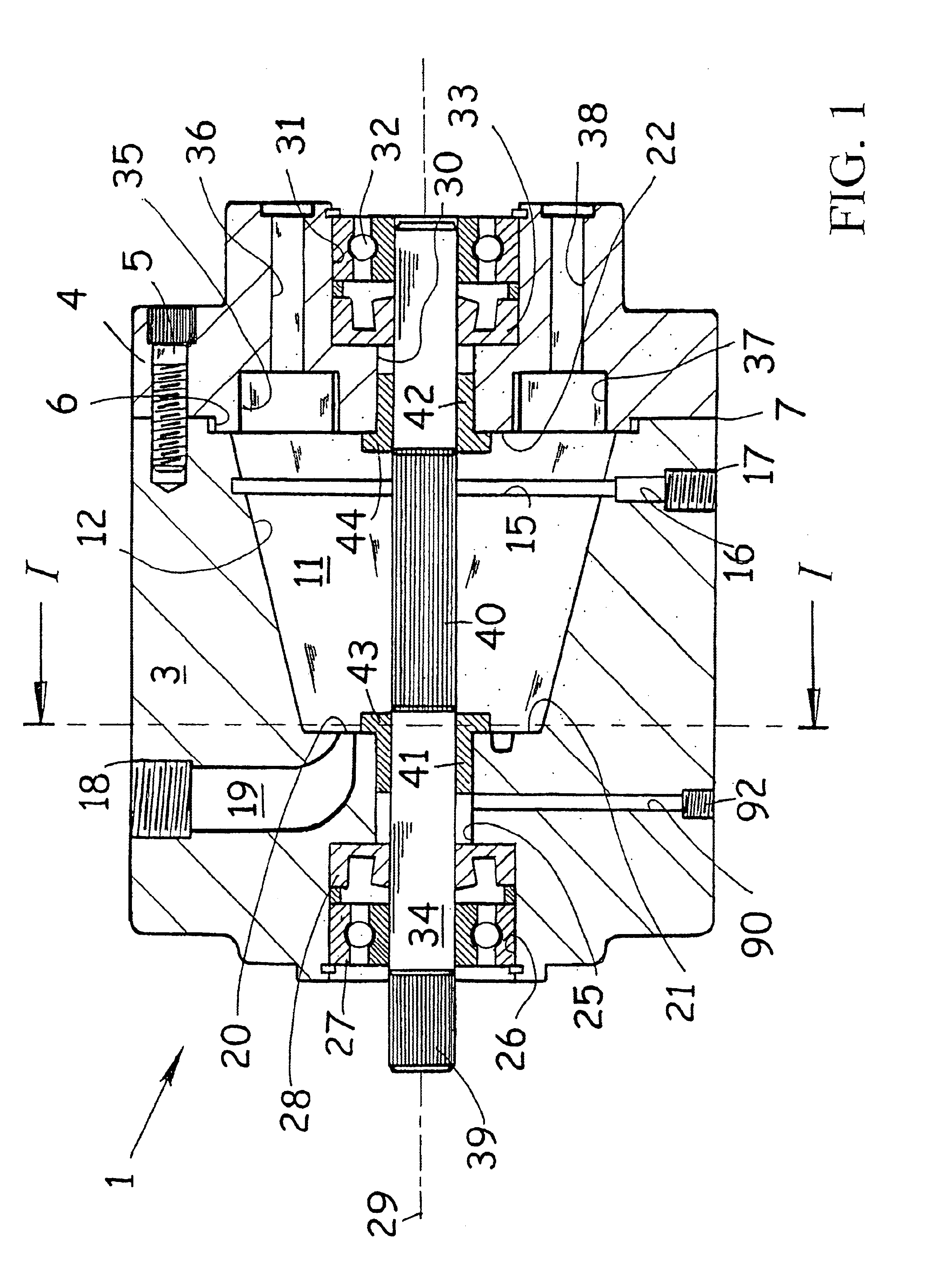
[0057]As shown, housing element 100 is fastened to housing element 4 by a plurality fastening screws 5, the two housing elements 100, 4 being registered together at 6 ensuring the accurate alignme...

third embodiment

DETAILED DESCRIPTION OF THE INVENTION

[0058]As the third embodiment of the present invention is a hybrid of the first and second embodiments of the invention, as such, only those features that differ will be here now described.

[0059]In FIG. 9, the inner surface 120 for the main chamber 123 in housing element 125 as well as outer surface 128 of the rotor assembly 130 remain conical as was the case in the first embodiment of the invention. However, here first and second boundary defining surfaces are angularly inclined with respect to the rotating axis by different amounts. Note therefore that the inner surface 120 in housing element 125 is angularly inclined by an angle depicted by “a” from the horizontal axis shown as 140 whereas the outer surface 128 of the rotor assembly 130 is angularly inclined by an angle depicted by “b” from the horizontal; axis shown as 140. Horizontal axis 140 is shown lying parallel and offset with respect to rotation axis 29 of drive shaft 34.

[0060]With thi...

fourth embodiment

DETAILED DESCRIPTION OF THE INVENTION

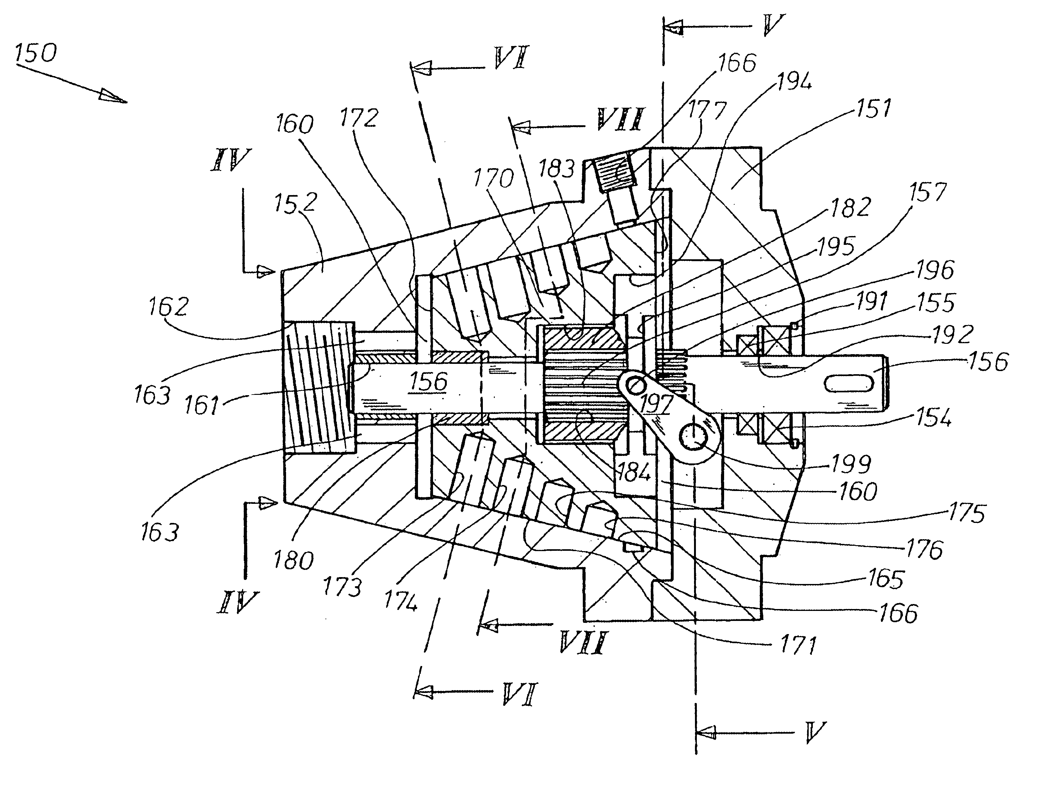
[0068]Referring first to FIGS. 10 to 12, the device as designated by reference numeral 150 has a housing structure comprising two elements 151, 152 joined together by a series of socket head cap screws 153. Housing element 151 is provided with a bearing 154 and a seal 155 through which drive-shaft 156 passes through. Drive-shaft 156 is provided with a spline 157 near its mid-point and extends into the interior chamber denoted by numeral 160, of the device 150, and further supported by bearing 161 located in housing element 152. Bearing 161 lies adjacent to the fluid inlet 162 and where four ports 163 are provided, positioned radially outwardly of bearing 161, to connect fluid inlet 162 with interior chamber 160. The interior of housing element 152 includes a inner surface 165, smaller in diameter nearer to inlet ports 163 and increasingly of larger diameter in the axial direction towards housing element 151. The surface is angularly inclined with...


PUM


Abstract

The apparatus has a housing with a main chamber in which a rotor is situated. A drive shaft drives the rotor about a longitudinal axis of rotation. The housing has a fluid inlet and a fluid outlet, the fluid inlet communicating with an inlet region and a fluid outlet communicating with an exit region. The outer surface of the rotor forms one boundary for the fluid heat generating region and is confronted by the inner surface of the main chamber which is the other boundary. At least one of these surfaces is angularly inclined relative to the axis of rotation of the drive shaft and rotor. By bodily shifting the rotor in a direction along the longitudinal axis, an increase or decrease in the distance between the outer and inner surfaces is possible in order to adjust for wear or to change the degree of shear experienced by the passing fluid.

Description

REFERENCE TO RELATED APPLICATION[0001]This application is a Continuation-in-Part of application Ser. No. 10 / 308,027; filed Dec. 3, 2002, the disclosure of which is incorporated in its entirety by the reference hereto.BACKGROUND OF THE INVENTION[0002]This invention relates generally to the heating of liquids, and specifically to those devices wherein rotating elements are employed to generate heat in the liquid passing through them. Devices of this type can be usefully employed in applications requiring a hot water supply, for instance in the home, or by incorporation within a heating system adapted to heat air in a building residence. Furthermore, a cheap portable steam generation could be useful for domestic applications such as the removal of winter salt from the underside of vehicles, or the cleaning of fungal coated paving stones in place of the more erosive method by high-pressure water jet.[0003]Joule, a wealthy Manchester brewer and English physicist who lived during the 19th...

Claims


Application Information

Patent Timeline
Patent Type & Authority Patents(United States)
IPC IPC(8): F24J3/00
CPCF24J3/003F24V40/00
Inventor THOMA, CHRISTIAN HELMUT
Owner THOMA CHRISTIAN HELMUT
Why Eureka
Try Eureka