Liquid container and inkjet cartridge

a technology of inkjet cartridges and liquid containers, applied in printing and other directions, can solve the problems of low efficiency of ink containing ink tanks using porous members, limited layout of constituent parts to achieve a required head difference, and large device, and achieves stable negative pressure characteristics, simple structure, and high durability.

Inactive Publication Date: 2005-11-01
CANON KK
View PDF21 Cites 23 Cited by
  • Summary
  • Abstract
  • Description
  • Claims
  • Application Information

AI Technical Summary

Benefits of technology

[0038]A planar member is secured to a surface of a convex apex formed on the sheet member in advance, the planar member is in contact with the spring to stabilize deformation of the sheet and stabilize a negative pressure.
[0039]There is provided a liquid container, an inkjet cartridge, and an inkjet recording apparatus in which a liquid can be supplied in a wide region with a negative pressure in a predetermined preferable range when the ink is extracted and which exhibit stable negative pressure characteristics.
[0040]There is provided a liquid container whose gas blocking properties are prevented from being deteriorated for a long time with a simple structure.
[0041]There is provided an ink tank having a structure that exhibits high durability even when ink is repeatedly charged and used, exhibits high ink utilization, and does not adversely affect ejecting performance of a printing head.
[0042]There is provided a structure which contributes to an inkjet printing head and a printing apparatus capable of a stable ejecting operation.
[0043]There is provided an ink tank container that is compact and simple in configuration even when plural types of inks are to be used, thereby contributing to an inkjet printing head and a printing apparatus capable of a stable ejecting operation.

Problems solved by technology

However, since the ink supply channel is an enclosed type, there is a need for a supply line such as a tube extending from an ink containing bag to an ink-consuming section (head section) located above the same, which results in a large device.
Further, limits are put on the layout of constituent parts to achieve a required head difference.
The ink containing efficiency of such an ink tank utilizing a porous member is basically low because of the presence of the porous member.
However, the use of a porous member is still unsatisfactory when a further improvement of ink containing efficiency is considered.
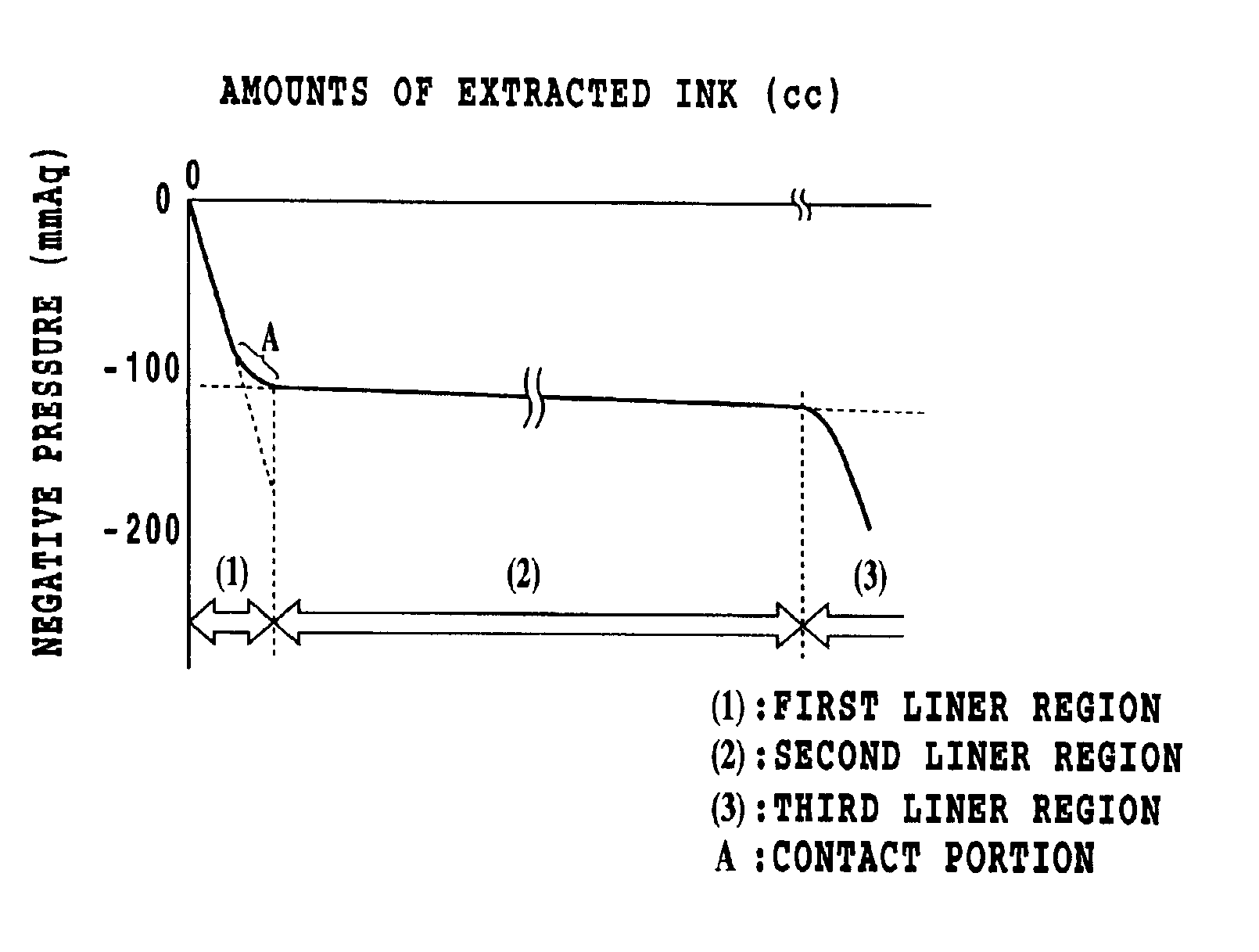
However, such an ink tank in the related art utilizing a spring and a sheet may have a problem associated with negative pressure characteristics of the same in that the range in which ink can be supplied with a stable negative pressure is small or in that the behavior of the negative pressure is unstable.
The shape of the sheet material of such a tank is likely to vary for reasons associated with manufacture, and this results in high possibility of variations of the shape of the sheet material when ink is extracted.
This may result not only in unstable ink supply but also in an increase in the amount of extracted ink in regions where an initial negative pressure is not in the preferable range, for example.
An ink tank having a relatively large capacity is practicable in spite of the fact that it still has variations and unstableness as described above because the force of the spring to generate a negative pressure is great and the rigidity of the sheet that changes according to the amount of ink is therefore relatively small.
However, the above-mentioned problem becomes more significant when such a configuration in the related art is used for an ink container having a relatively small capacity (e.g., a capacity up to 30 cc).
In particular, since the amount of ink that is used under a negative pressure in an unpreferred range increases, it may not be possible to extract a sufficient amount of ink in a preferable state of supply.
Such a method of manufacture may result in a reduction of yield or variation of the ink capacity itself.
In the case of an ink tank in which no spring is provided and in which a negative pressure is generated by changing the thickness of the sheet to control the rigidity of the sheet, a problem arises in that the deformation of the sheet as a result of ink consumption likely to vary and in that the variation of the negative pressure becomes more significant when changes in the sheet rigidity according to the ambient temperature are taken into consideration.
In the case of an enclosed type liquid container, however, ink meniscuses can be broken to lead to leakage of ink from the ink ejection port when the internal pressure of the container increases to reach or exceed a meniscus holding pressure at the ejection port as a result of inflow of gasses.
In particular, except for soft films used in the related art taking gas blocking properties into consideration, the gas blocking properties of materials used for a rigid structural member forming an ink container or recording head may not be so good because they are selected for less influence on ink and capability of being bonded to a sheet.
This increases a dead space in an ink tank and adversely affects ink utilization.
When a plurality of bent sections and a leaf spring are used, there will be a great spring load, which is unpreferred in that a negative pressure that is greater than an adequate value is generated especially when an ink tank is configured compactly.
When a deforming load is repeatedly applied to the spring, fatigue occurs at the bent portion, which can finally result in breakage.
Further, the spring must have a certain radius of curvature to be bent, which results in a dead space that is equivalent to the radius of curvature when the spring is completely compressed just as in the case of the use of a coil spring.
Specifically, a semi-elliptic spring is not suitable for an ink tank having a configuration in which ink is repeatedly charged and used, and it also has problems to be solved with respect to ink utilization.
While the same publication has disclosed a configuration in which movable parts are formed symmetrically on both sides of a semi-elliptic spring, a force to deform the movable parts can act off balance because of the presence of a bent portion, which can result in unstable deformation of the movable parts or can cause variations of deformation of the movable part on one side to adversely affect the movable part on the other side through the semi-elliptic spring.
Resultant fluctuations of the pressure in the ink tank can act on the printing head through the ink supply channel to adversely affect the ejecting performance.
However, a configuration in which a plurality of ink tanks are provided for color recording results in an increase in the size of an apparatus in contradiction to needs for more compact recording apparatus.
Although efforts have been made to provide a plurality of ink tanks close to each other for this reason, it is rather difficult to provide a plurality of ink tanks close to each other because of mechanical restrictions placed by an ink supply connecting section on a printing head main body for ejecting ink in each color.
The above-described arrangements create a problem especially when a configuration is adopted in which ink is supplied by attaching ink tanks integrally with or detachably from a printing head that is mounted on a carriage to be moved back and forth (main scanning).
Specifically, when members moving with a carriage (a printing head and ink tanks undetachably or detachably integrated with the same) have a large projected area in the direction of a plane perpendicular to the direction of main scanning or a large volume, a grate space will be required for main scanning, which will result in an increase in the size of the apparatus as a whole.

Method used


Image

  • Liquid container and inkjet cartridge
  • Liquid container and inkjet cartridge
  • Liquid container and inkjet cartridge

Examples


Embodiment Construction

[0108]Various embodiments of the invention applied to inkjet recording apparatuses will now be described with reference to the drawings.

[0109]FIG. 1 is a partially cutaway perspective view of an ink or liquid container according an embodiment of the invention. FIGS. 2A, 2B, and 2C are a sectional view of the ink container in FIG. 1 taken on a Z-X plane in the figure, a sectional view of the same taken on an X-Y plane, and a view of the same taken in an X-direction with the outer case removed at one side thereof, respectively.

[0110]As shown in those figures, the ink container 310 of the present embodiment has movable members 311 provided on both sides of a frame 318 in the form of a substantially rectangular loop and flat plates 314 mounted to movable members 311. That is, an ink containing space is formed by those members. An outer case 313 of the ink container 310 serves as a shell for protecting the members such as the movable members 311 against an external force.

[0111]The movabl...


PUM


Abstract

In a structure of an ink tank having a deformable sheet that constitutes the tank and a spring for imparting a negative pressure, unstableness of the negative pressure attributable to the deformation of the sheet as a result of ink consumption is prevented. For this purpose, a plate-like member is joined to a top section of the sheet formed in a convex shape, and the spring for generating the negative pressure in the tank is mounted to the same member. This makes it possible to maintain a high volume ratio of the ink tank and to achieve stableness of the negative pressure by adequately regulating the deformation of the sheet when the sheet is displaced in the direction of retracting toward the interior of the tank as a result of a reduction of the amount of ink in the tank.

Description

[0001]This application is based on Japanese Patent Application Nos. 2001-246234 filed Aug. 14, 2001, 2001-246236 filed Aug. 14, 2001, 2001-246238 filed Aug. 14, 2001, 2001-246239 filed Aug. 14, 2001 and 2001-398217 filed Dec. 27, 2001, the content of which are incorporated hereinto by reference.BACKGROUND OF THE INVENTION[0002]1. Field of the Invention[0003]The present invention relates to a liquid container, e.g., a liquid container that utilizes a negative pressure to supply a liquid such as ink from the inside of the liquid container to a pen or an inkjet recording head as a recording section. The invention also relates to an inkjet cartridge provided by integrating a liquid container as an ink tank and an inkjet recording head.[0004]2. Description of the Related Art[0005]Known containers for containing a liquid include containers that supply a liquid to the outside with a negative pressure maintained inside the containers. A container of this type is characterized in that a liqu...

Claims


Application Information

Patent Timeline
Patent Type & Authority Patents(United States)
IPC IPC(8): B41J2/175
CPCB41J2/17509B41J2/17513B41J2/17556B41J2002/17516B41J2/175
Inventor OGURA, HIDEKIOTSUKA, NAOJIINOUE, HIROYUKIISHINAGA, HIROYUKIKUWABARA, NOBUYUKIOHASHI, TETSUYAINOUE, RYOJI
Owner CANON KK
Why Eureka
Try Eureka