
Electroluminescence (EL) tube and wire and manufacturing method

a technology of electroluminescence and electroluminescence powder, which is applied in the direction of power cables, cables, insulated conductors, etc., can solve the problems of poor luminescent quality and effect, high cost of luminescent wires, etc., and achieves simple manufacturing process, high luminescent area, and high tensile strength

Inactive Publication Date: 2005-11-01
SHENZHEN EL LIGHTING TECH CO LTD
View PDF12 Cites 16 Cited by
  • Summary
  • Abstract
  • Description
  • Claims
  • Application Information

AI Technical Summary

Benefits of technology

[0005]The primary object of the present invention is to overcome the above-mention deficiencies of conventional manufacturing techniques and, by using the same materials and under the same conditions of conventional luminescent wire products, to provide a luminescent wire product with simple structure and manufacturing techniques, low cost, stable luminescent effect, and reliable quality.
[0007]This invention further provides a kind of metal or non-metal luminescent tube that is lighter, softer, and with larger luminescence area and lower cost compared with conventional columned luminescent body made of several luminescent wires running side-by-side.
[0009]Transparent thermoplastic compound or synthetic resin has good insulating and dielectric performance, and can form an insulating capsule outside the particles of luminescent powder when mixed with it. The luminescent layer made of this mixture can be directly covered or spread on central electrode, which process can omit the necessity of using insulating medium layer made of inorganic material, the barium titanate powder, and helps reducing manufacturing cost.
[0014]This invention further provides a new structure and new technique that can help enlarging luminescent area of linear luminescent body. Generally, for enlarging the luminescent area of linear luminescent body, people usually need to increase the diameter of the solid core linear central electrode. However, with the increase of diameter of central electrode wire, the linear luminescent body usually shows a reduced flexibility and larger weight. On the other hand, the diameter of central electrode wire of linear luminescent body cannot be increased limitlessly. It is recommended the diameter not exceed 2 mm. Here we use a hollow wire as central electrode, i.e. using metal or non-metal conductive soft tube as the central electrode of linear luminescent body. The tubular luminescent body achieved not only has a double-sized luminescent area, but also is light-weighted and much flexible.
[0015]For increasing the flexibility of tubular luminescent body, the conductive soft tube can be made of metal soft tube, corrugated tube, single or double hook flexible sheath, flexible tube weaved using metal or non-metal fine wires, conductive plastic tube, conductive rubber tube, or flexible tube with metal coating.
[0019]The luminescent wire and tube products of this invention are light-weighted, flexible, with large luminescent area, tensile strength, and simple manufacturing process allowing consecutive industrial production, and can be applied extensively in decoration, advertisement, craftwork weaving and other areas.

Problems solved by technology

Complicated structure and manufacturing techniques and difficulties for controlling the quality of penetration of filling liquid and the blocking effects of blocking layer, all these have made this kind of luminescent wire not only of high cost, but also with bad luminescent quality and effect.

Method used


Image

  • Electroluminescence (EL) tube and wire and manufacturing method
  • Electroluminescence (EL) tube and wire and manufacturing method
  • Electroluminescence (EL) tube and wire and manufacturing method

Examples


Embodiment Construction

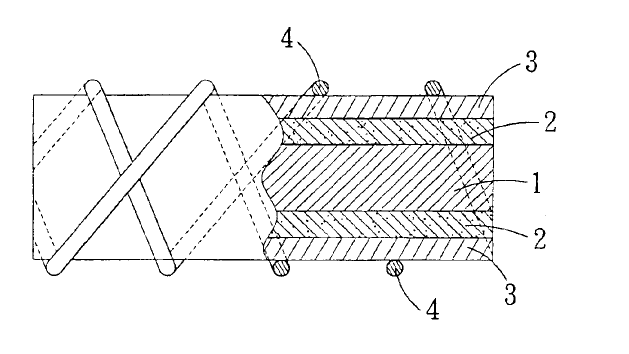
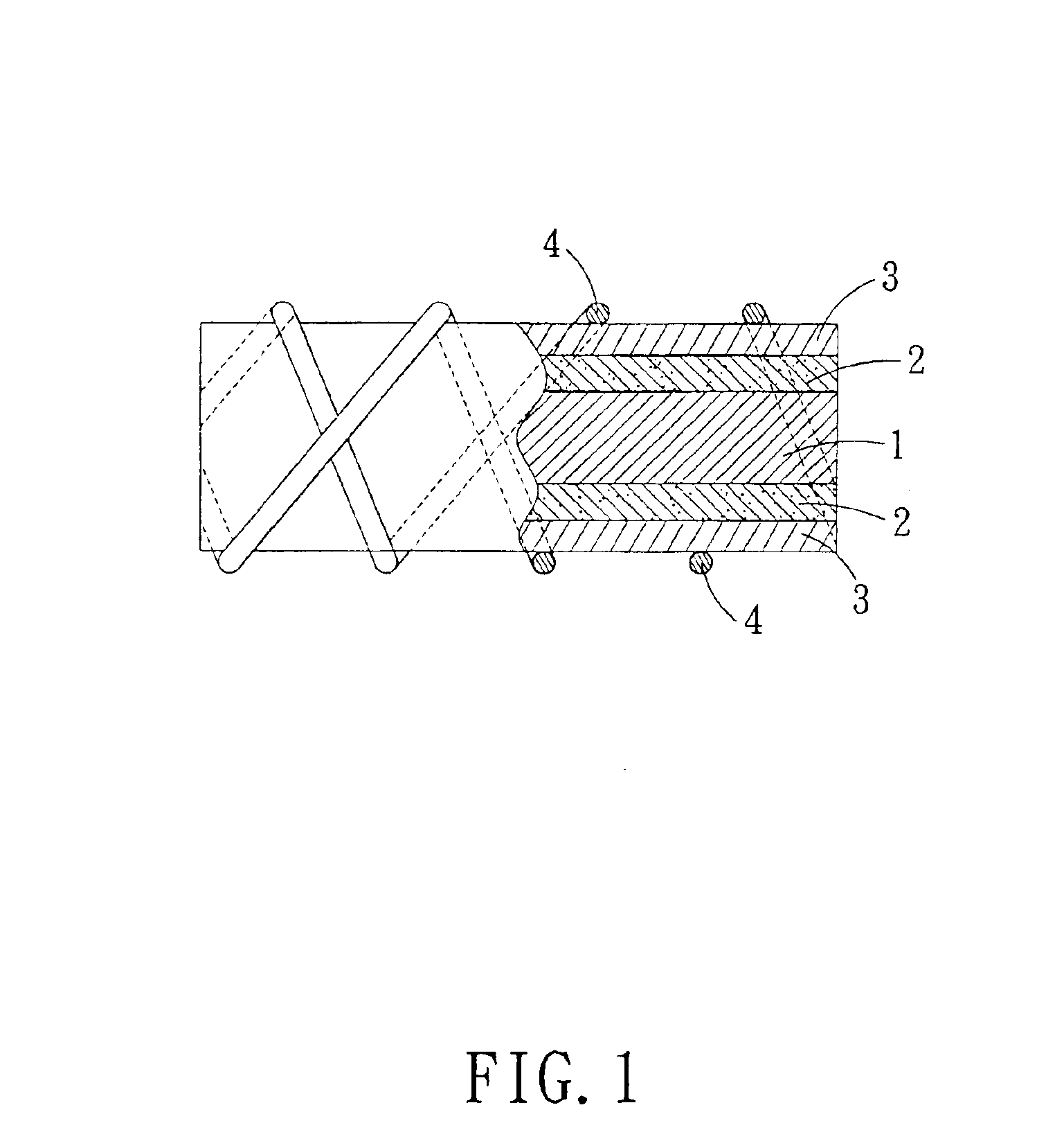
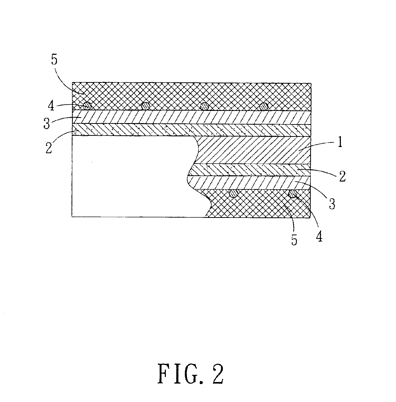
[0030]Referring to FIG. 1, wherein a core of luminescent body has a central electrode made of metal or non-metal wire 1. A luminescent layer 2 consisted of a mixture of luminescent powder 6 and transparent macromolecular polymer, or polyurethane resin, or organic silicon resin 7, is coated on the outer surface of the central electrode. On the circular surface of luminescent layer 2, there is a transparent electrode layer 3 and an accessory electrode 4 wound on it. With reference to FIG. 2, wherein on the core of luminescent wire shown in FIG. 1, a layer of transparent polymers 5 made from PVC, EVA, or others, is coated to form a linear luminescent body.

[0031]Besides metal or non-metal wire 1, metal or non-metal flexible tube 8 can also be used as central electrode See in FIG. 3.

[0032]As shown in FIG. 1, the winding structure of accessory electrodes used in this embodiment includes at least two accessory electrodes 4, which are wound on the axial outer surface of the transparent laye...


PUM

PropertyMeasurementUnit
thicknessaaaaaaaaaa
thicknessaaaaaaaaaa
diameteraaaaaaaaaa

Abstract

An electroluminescent wire core having a flexible central electrode, a luminescent layer and a transparent, conductive layer. An outer surface of the central electrode is coated with the luminescent layer and the transparent, conductive layer respectively. In the transparent, conductive layer is disposed luminescent power which is covered by thermoplastic macromolecular polymer and synthetic resin.

Description

BACKGROUND OF THE INVENTION[0001]1. Field of the Invention[0002]The present invention relates to the field of luminescent source of electroluminescence (EL) powder, and more particularly to a flexible linear or tubular luminescent body and relevant manufacturing techniques.[0003]2. Description of the Prior Arts[0004]According to the conventional manufacturing method and structure of EL powder-based luminescent wire, the outer surface of a metal electro-conductive wire will be covered with a layer of insulating medium, which outer surface will be further covered with a mixture of luminescent powder and adhesive. Finally, the outer surface of this layer of mixture will be sprayed with another layer of transparent electrode made of metal. The adhesive in the layer of mixture will be volatilized and left with pores filled with air, which can reduce the field capacitance of luminescent source and form small black spots. For filling these pores, generally some special devices will be used...

Claims


Application Information

Patent Timeline
Patent Type & Authority Patents(United States)
IPC IPC(8): H05B33/10H05B33/14
CPCH05B33/10H05B33/145
Inventor ZHENGKAI, YINZUMI, LU
Owner SHENZHEN EL LIGHTING TECH CO LTD
Learn More