
Enhanced CMOS circuit to drive DC motors

a dc motor and cmos technology, applied in logic circuit coupling/interface arrangement, electronic switching, pulse technique, etc., can solve the problems of low output current, low production cost of hybrid bicmos circuit, and limited range of conventional cmos transistors

Inactive Publication Date: 2005-11-01
AVID ELECTRONICS CORP
View PDF2 Cites 0 Cited by
  • Summary
  • Abstract
  • Description
  • Claims
  • Application Information

AI Technical Summary

Benefits of technology

"The present invention provides an enhanced CMOS circuit that can form a driver circuit for DC motors used in portable CD players. The circuit is able to lower the driving impedance of a CMOS conduction channel and boost current gain, thus producing sufficient output current to drive a DC motor. The circuit is formed using a MOS fabrication process, which reduces production costs. The invention also provides a CMOS driver circuit that combines control circuits and driver circuits on the same chip. The driver circuit is formed by a pair of NMOS transistors connected in series, with one end connected to a positive power supply terminal and the other end connected to ground or a negative power supply terminal. The invention enables the combination of control circuits and driver circuits on the same chip using a MOS process alone without the Bi-MOS process. The invention also provides a method for reducing the driving impedance of a CMOS conduction channel and boosting current gain to drive a DC motor."

Problems solved by technology

However, the production costs of hybrid BiCMOS circuits are higher than those for CMOS circuits.
But conventional CMOS transistors have their own limitations.
The small output current, due to the inherent driving impedance, is insufficient to drive a DC motor or other digital motors.
Using this method will increase the size of the integrated circuit, which is contrary to current efforts to downsize components.
However, the CMOS generally exhibits low voltage endurance, thus it poses a challenge for circuit designers to maintain the operating voltage of CMOS circuits below 5V.
Hence, using the conventional CMOS technology, output current cannot be effectively increased to meet the requirements of large current applications.
But then the combination of BiCMOS and CMOS transistors on the same chip requires much more complex processes.

Method used


Image

  • Enhanced CMOS circuit to drive DC motors
  • Enhanced CMOS circuit to drive DC motors
  • Enhanced CMOS circuit to drive DC motors

Examples


Embodiment Construction

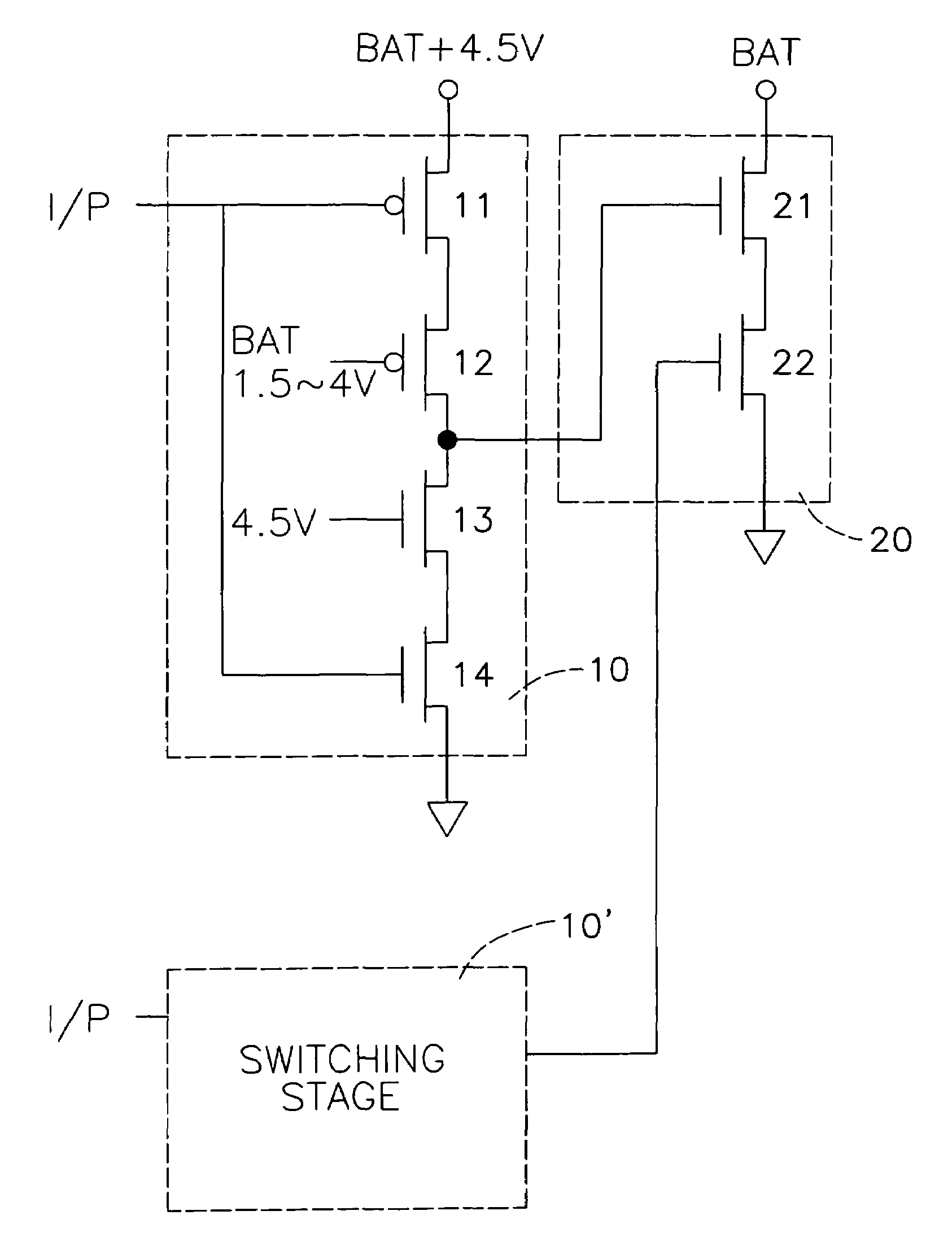
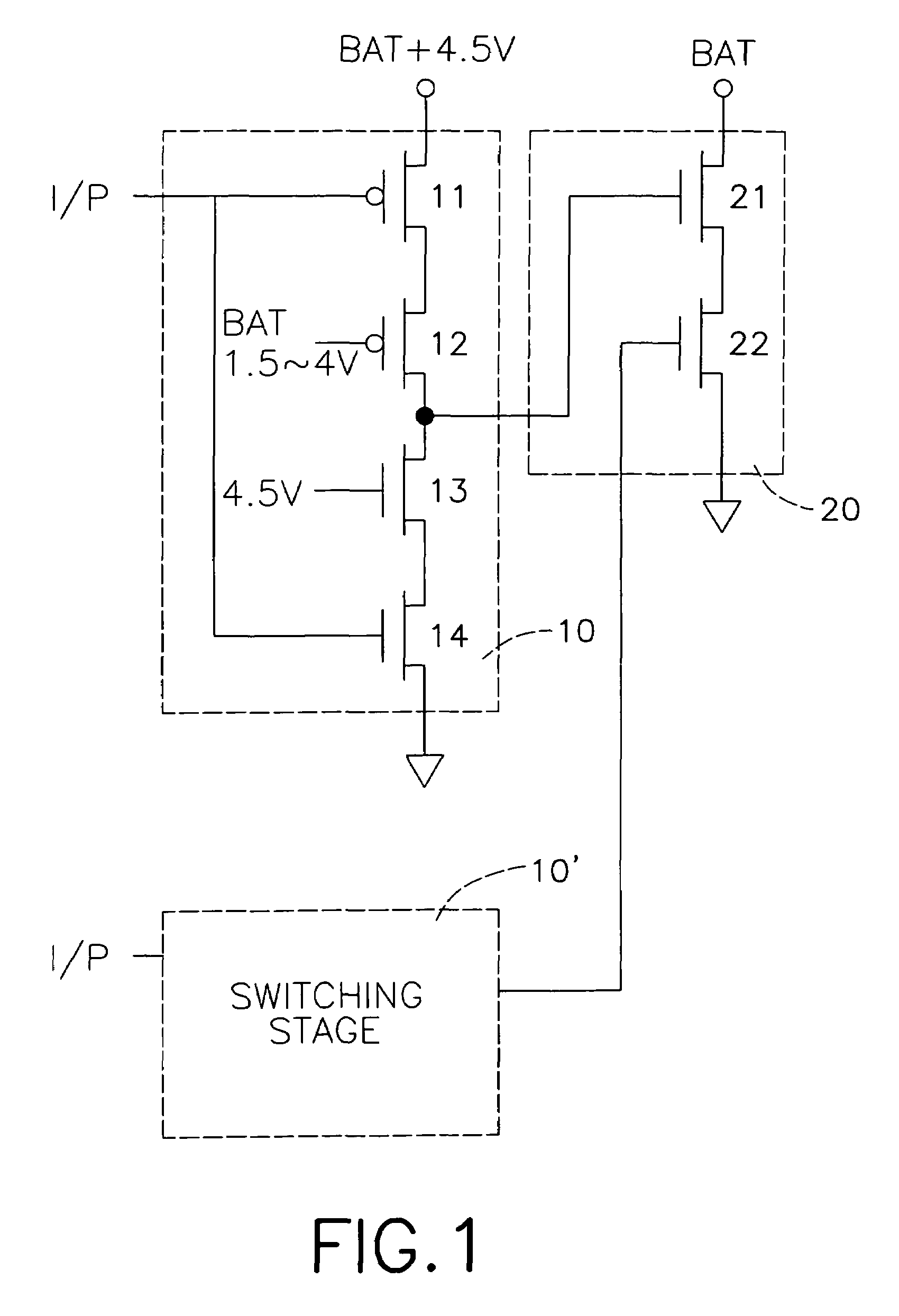
[0024]The driver circuit of a DC motor used in a portable CD player is shown in FIG. 1, comprising at least a first and a second switching stage (10) (10′) (only the first switching stage (10) is shown in the diagram) and a driver stage (20).

[0025]The first switching stage (10) is formed by a pair of PMOS transistors (11) (12), connected in series, and a pair of NMOS transistors (13) (14), also connected in series, to form a push-pull circuit.

[0026]One end of the switching stage (10) is connected to a positive power supply terminal with a higher voltage, whilst another end is connected to ground or to negative power supply terminal. In the present example, the supply voltage of the positive power supply terminal is the summation of output voltages of the first DC power supply (1.5–4 V) and the second DC power supply (4.5 V).

[0027]The node connecting the pair of PMOS transistors (11) (12) and the pair of NMOS transistors (13) (14) acts as output of the switching stage (10). One of th...


PUM


Abstract

An enhanced CMOS circuit to drive a DC motor is disclosed, in which a CMOS circuit is used to form a driver circuit of the DC motor, replacing a conventional BiCMOS for the part of the driver circuit, which is used in a portable CD player. Two switching stages are each formed by four CMOS transistors connected in series, with one end of the circuit being connected to a positive power supply with a higher voltage and another end connected to ground or negative power supply terminal. The switching stages are able to produce high output voltages, which are applied on the gates of the CMOS transistors in the driver stage to lower the driving impedance of the conduction channel and to produce sufficient output current to drive a DC motor.

Description

BACKGROUND OF THE INVENTION[0001]1. Field of the Invention[0002]The present invention is related to using an enhanced CMOS circuit to form a driver circuit of a DC motor, and more particularly to an enhanced CMOS circuit that is able to boost current gain, replacing the BiCMOS circuit for the part of the driver circuit, in order to produce sufficient output current to drive a DC motor of a portable CD player. Also, the present invention enables the combination of different control circuits to be formed on the same chip using an MOS process with lower production costs.[0003]2. Description of Related Art[0004]A BiCMOS circuit contains both bipolar junction transistors and CMOS transistors, allowing for advantages of both processes to be exploited. Bipolar circuits are inherently faster than the CMOS, and have shorter signal delay and faster switching speed, making them suitable for high frequency applications such as operation amplifiers, but CMOS circuits are preferred where low powe...

Claims


Application Information

Patent Timeline
Patent Type & Authority Patents(United States)
IPC IPC(8): H01L21/70H01L21/822H03K19/0175H03K19/094H01L27/04H03K17/695H02P7/00H03K17/06H03K17/10H03K17/687
CPCH03K17/063H03K17/6871H03K17/102
Inventor LIN, WAN-JUNG
Owner AVID ELECTRONICS CORP
Learn More