C-shaped cross section tubular ophthalmic implant for reduction of intraocular pressure in glaucomatous eyes and method of use

a glaucomatous eye and intraocular pressure technology, applied in the field of tubular shunts for the control of intraocular pressure in glaucomatous eyes, can solve the problems that the pressure from the anterior chamber may not always be sufficient to separate the capsule, and achieve the effects of reducing the diameter of the bleb, preventing the migration of the implant, and adjusting the total surface area

Inactive Publication Date: 2005-11-08
AQ BIOMED LLC
View PDF6 Cites 168 Cited by
  • Summary
  • Abstract
  • Description
  • Claims
  • Application Information

AI Technical Summary

Benefits of technology

[0020]Another object of the present invention is to provide an anchor for the implant, which is attachable to the sclera at the limbus. This has the advantage of preventing migration of the implant into the anterior chamber.
[0021]Another object of the present invention is to provide a further three-fold reduction in bleb diameter resulting in a capsule only one cell layer thick, with the advantage that the resultant structure approaches the dimensions of the trabecular meshwork in a human eye.
[0022]Another object of the present invention is to provide a post-surgical ability to customize the total surface area of the implant by increasing filtration surface area without the need of further surgery or an additional implant by simply removing, after post-surgical intraocular pressure has been determined, a ligature or series of ligatures located at intact portions along the length of the insert situated between C-shaped, open, cross-sectional portions.
[0023]Another object of the present invention is to provide an implant with a resultant reduced surface tension on the wall of the implant with the advantage that fibrosis is minimized, thereby allowing continuous and on-going hydraulic conductivity of aqueous with a concomitant reduction in intraocular pressure to a safe and stabilized level.
[0024]Another object of the present invention is to provide an implant nidus with a scalloped cross-section whereby separation of the fibrous tissue of the bleb from the implant nidus is facilitated and the cross-sectional dimension of the nidus may be reduced as compared to a smooth, round surface.
[0025]Another object of the present invention is to provide a method for reducing intraocular pressure by creating a cylindrical bleb for producing improved accessory filtration by implanting a cylindrical tube having a proximal end and distal end, the distal portion of the cylindrical tube side wall being removed, into an eye to serve as a nidus for a conduit of aqueous humor to bypass angle structures.

Problems solved by technology

If the capsule or bleb is deposited onto a smooth, solid surface, pressure from the anterior chamber may not always be sufficient to separate the capsule from the smooth, solid surface and inflate a volume in the subconjunctival space.

Method used


Image

  • C-shaped cross section tubular ophthalmic implant for reduction of intraocular pressure in glaucomatous eyes and method of use
  • C-shaped cross section tubular ophthalmic implant for reduction of intraocular pressure in glaucomatous eyes and method of use
  • C-shaped cross section tubular ophthalmic implant for reduction of intraocular pressure in glaucomatous eyes and method of use

Examples


Embodiment Construction

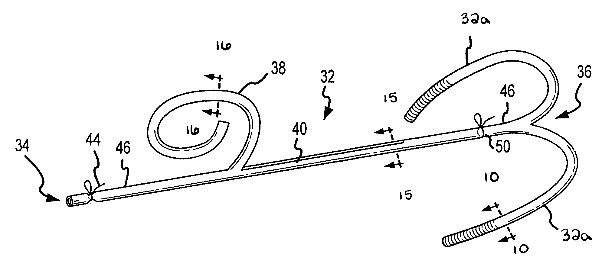
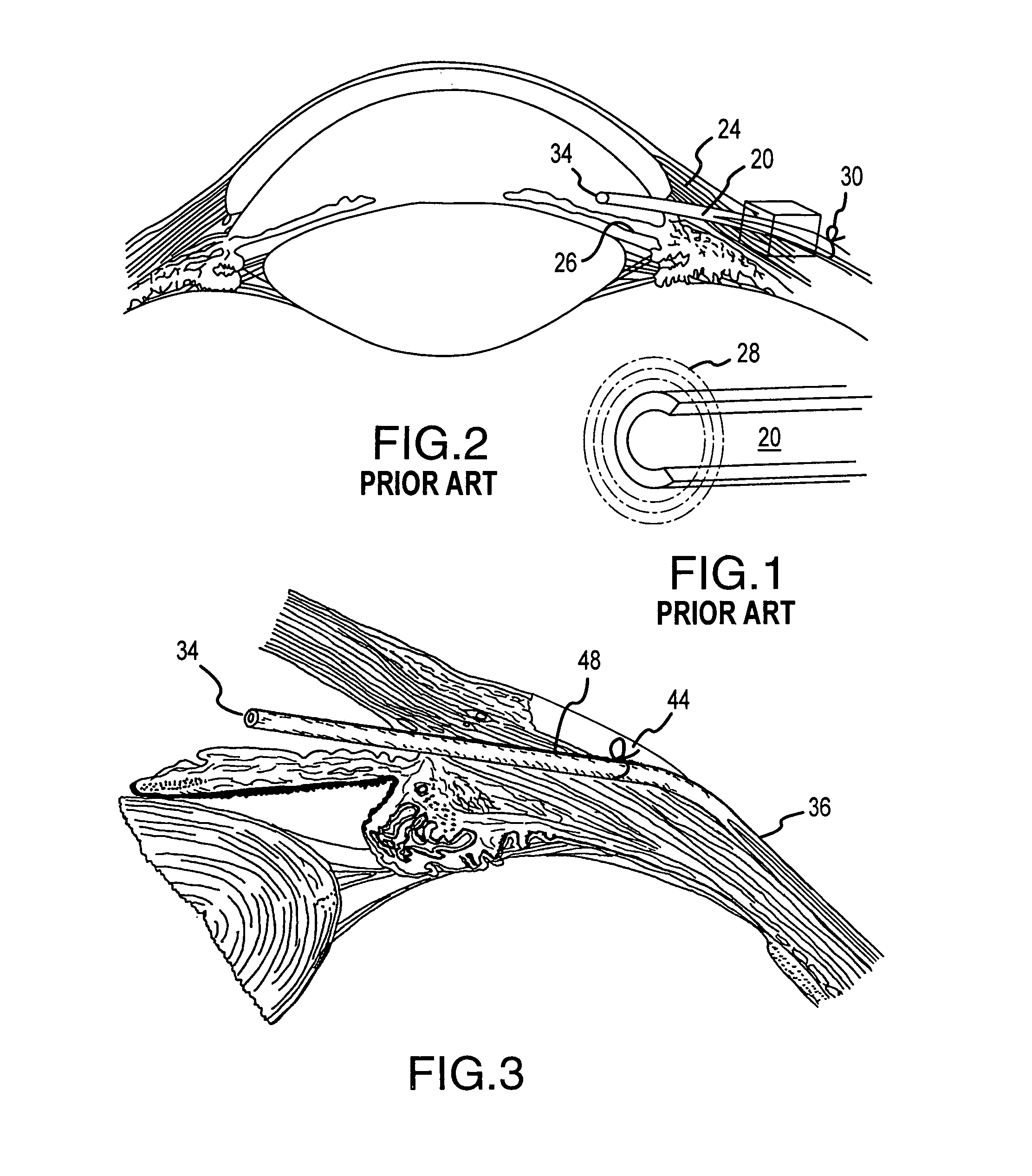
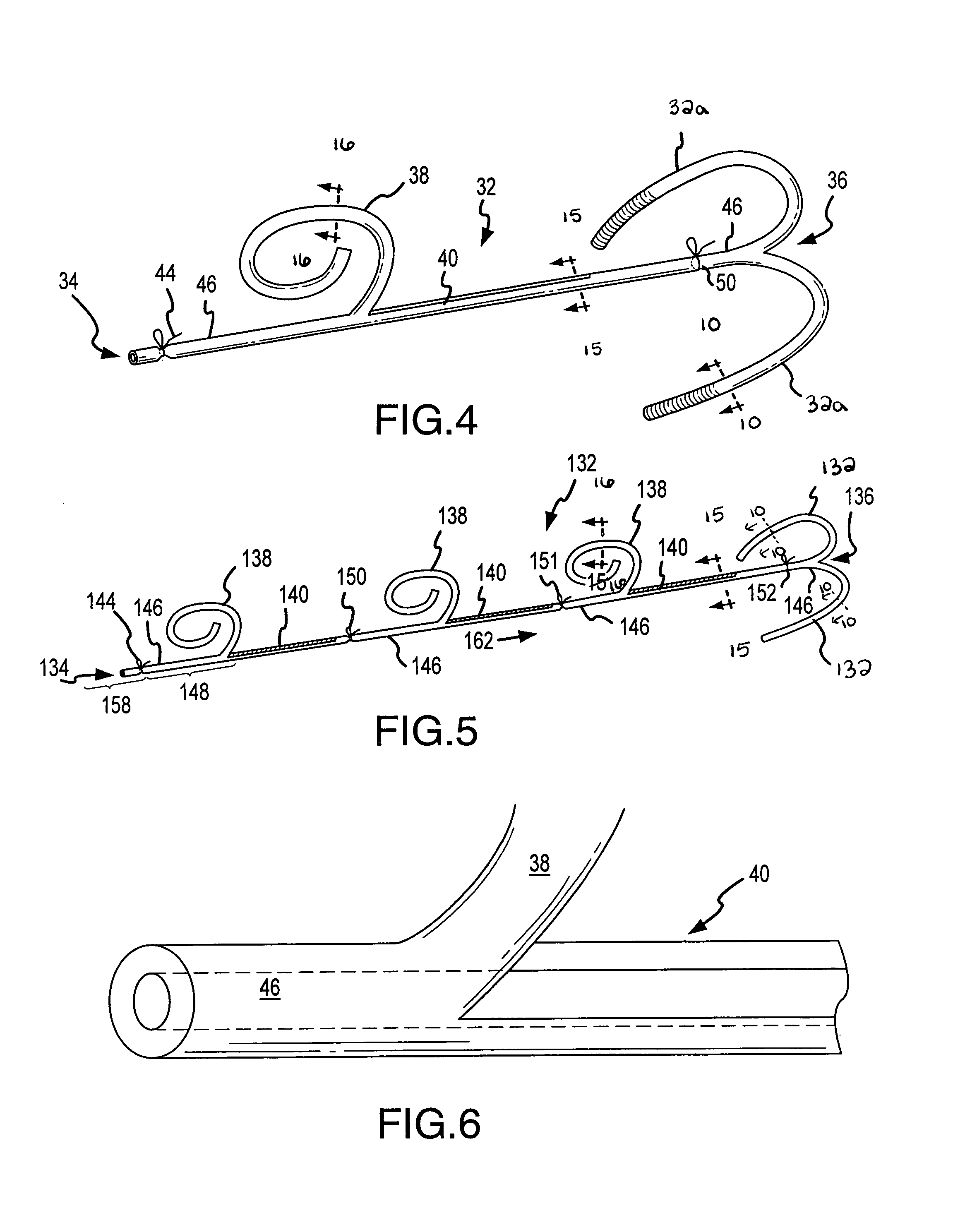
[0048]Referring now to FIG. 4 of the drawings, there is shown a schematic representation of the ophthalmic implant, cylindrical tube 32, with the proximal end 34 shown on the left and the distal end 36 shown on the right. It is to be noted that tube 32 may be and includes tubes of a cross-sectional shape other than circular, e.g. triangular, rectangular, pentagonal, L-shaped, etc. This is because the capsule formed around the tube when the capsule is inflated will be essentially a cylindrical shape as it is inflated by fluid. In practice, the conjunctiva is incised about 3 mm from the limbus and the conjunctiva is elevated by blunt dissection 10–12 mm back so that the longer distal end of the implant can be pushed into the pocket so formed. Through this same incision, a needle track is made entering the anterior chamber just in front of the iris. The proximal end 34 is inserted through this needle track 48, shown in FIG. 3, made by a 23 gauge needle. The small gauge ensures that lim...


PUM


Abstract

A tube for implantation into the eye for replacement conduction of aqueous humor from the chambers of the eyeball to the subconjunctival tissue and ultimately to the venous system is comprised of an elongated fluid conducting conduit having distal and proximate ends, a sidewall and an interior passageway and at least one longitudinally extending opening in the sidewall that exposes the interior passageway and at least one nidi-forming structure carried by the conduit and extending laterally therefrom to implement the formation of at least one aqueous filtration bleb in the tissue of the eyeball. In one embodiment, the tube also contains at least one releasable ligature circumscribing the conduit. In another embodiment, the tube also contains an anchor appended to the conduit to prevent it from migrating from its placement site.

Description

RIGHTS OF THE GOVERNMENT[0001]The invention described herein may be manufactured and used by or for the Government of the United States for all governmental purposes without the payment of any royalty.BACKGROUND OF THE INVENTION[0002]The present invention relates generally to tubular shunts for the control of intraocular pressure in glaucomatous eyes, and more specifically to a tubular shunt with a C-shaped radial cross section along portions of the tube and a method of controlling intraocular pressure.[0003]Glaucoma is a disease characterized by high pressure inside the eye, leading to the loss of retinal nerve fibers with a corresponding loss of vision. Glaucoma therefore is a disease affecting the optic nerve, the nerve bundle which carries visual information to the brain.[0004]The eyeball is basically a rigid sphere filled with fluid. Positive pressure inside the eye is needed to keep the retina attached to the back of the eye. Pressure is maintained by fluid production from a b...

Claims


Application Information

Patent Timeline
Patent Type & Authority Patents(United States)
IPC IPC(8): A61F9/00A61F9/007A61F2/14
CPCA61F9/0017A61F9/00781A61F2230/0065
Inventor WILCOX, MICHAEL J.
Owner AQ BIOMED LLC
Why Eureka
Try Eureka