Control circuit for a direct current motor

Inactive Publication Date: 2005-11-08
ROBERT BOSCH GMBH
View PDF11 Cites 21 Cited by
  • Summary
  • Abstract
  • Description
  • Claims
  • Application Information

AI Technical Summary

Benefits of technology

[0009]In addition, for control of the d.c. motor and for additional protection, the control of the d.c. motor may be clocked by another power MOSFET, and a control unit of the additional power MOSFET may be switched off by the polarity reversal

Problems solved by technology

Therefore, the traditional polarity reversal protection d

Method used


Image

  • Control circuit for a direct current motor
  • Control circuit for a direct current motor

Examples


Example

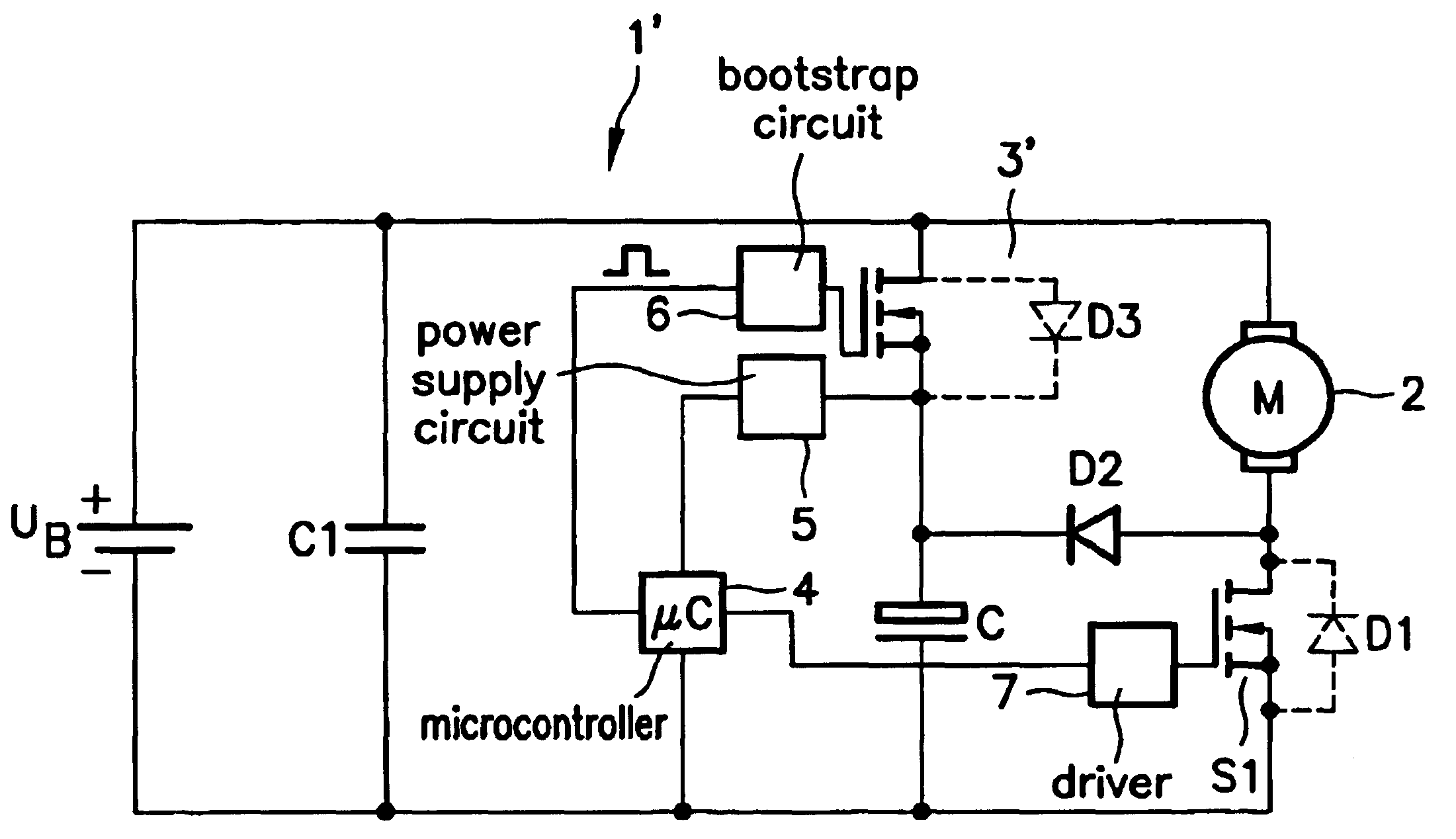
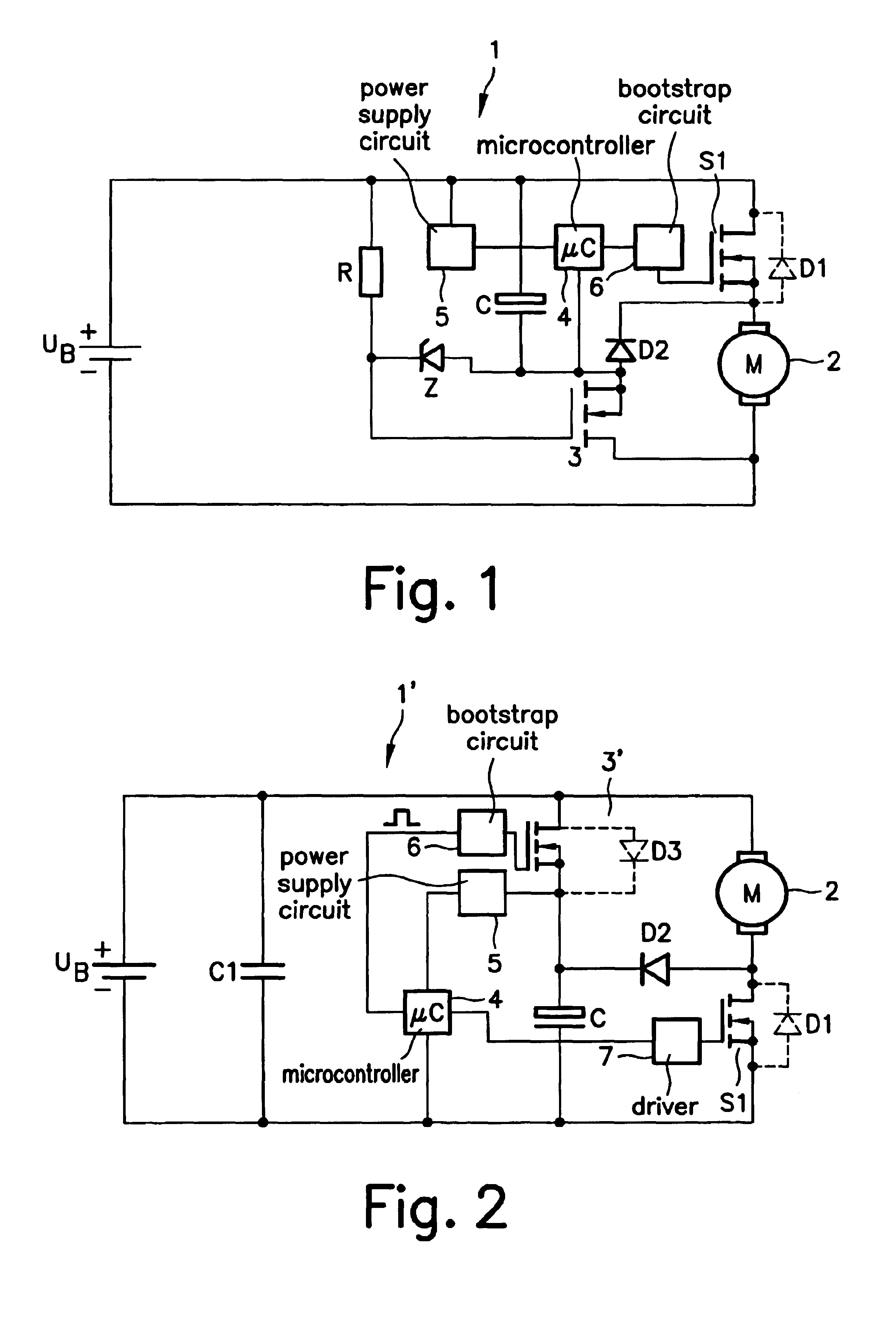
[0012]As FIG. 1 shows, a d.c. motor 2, clocked by a switching device S1 having an integrated diode D1, is connected to a battery voltage UB. An electrolytic capacitor C is connected to switching device S1 in parallel to d.c. motor 2 by way of a polarity reversal protection device 3 in the form of an n-channel power MOSFET operated inversely. In addition, a freewheeling diode D2 is also connected in parallel to d.c. motor 2 by way of polarity reversal protection device 3, with freewheeling diode D2 being connected at its cathode to the positive side of d.c. motor 2 and at its anode to the negative side of electrolytic capacitor C and the drain terminal of power MOSFET 3. The source terminal of power MOSFET 3 is connected to the negative side of d.c. motor 2, which is connected to the negative pole of battery voltage UB. The gate terminal of power MOSFET 3 is connected to positive battery voltage UB across a resistor R. A Zener diode Z is connected between the drain terminal and the g...


PUM


Abstract

The invention relates to a control circuit for a direct current motor with a reverse pole protection device, which is connected to the electric circuit of the electrolytic capacitor and the free-wheeling diode in order to reduce losses in the reverse pole protection device.

Description

FIELD OF THE INVENTION[0001]The present invention relates to a control circuit for a d.c. motor having an electrolytic capacitor connected in parallel to it, a freewheeling diode and a polarity reversal protection device with a transistor switch having a diode connected in parallel to it.BACKGROUND INFORMATION[0002]Such a control circuit is regarded as known. A polarity reversal protection device suitable for this purpose is described in German Patent No. 39 24 499, in particular with respect to FIG. 4D given there. Using such a polarity reversal protection device for a d.c. motor powered with a battery voltage prevents a short circuit over the freewheeling diode and an inverse diode of a power MOSFET provided for clocked control of the d.c. motor in the event of reversal of polarity of the battery voltage. Furthermore, the polarity reversal protection device prevents destruction of an electrolytic capacitor provided in the control circuit in the event of polarity reversal. With a k...

Claims


Application Information

Patent Timeline
IPC IPC(8): H02H7/08H02H11/00H02H9/04H02P7/06
CPCH02H7/0833H02H11/003H02H9/047
Inventor KESSLER, MARTINPREIS, KARL-HEINRICH
Owner ROBERT BOSCH GMBH
Why Eureka
Try Eureka