
Dynamic wake prediction and visualization with uncertainty analysis

a technology of uncertainty analysis and wake prediction, applied in the field of wake vortex avoidance, can solve problems such as adverse effects on airport capacity

Inactive Publication Date: 2005-11-08
NAT AERONAUTICS & SPACE ADMINISTATION THE UNITED STATES GOVERNMENT AS REPRESENTED BY THE ADMINISTATION OF THE THE
View PDF12 Cites 95 Cited by
  • Summary
  • Abstract
  • Description
  • Claims
  • Application Information

AI Technical Summary

Benefits of technology

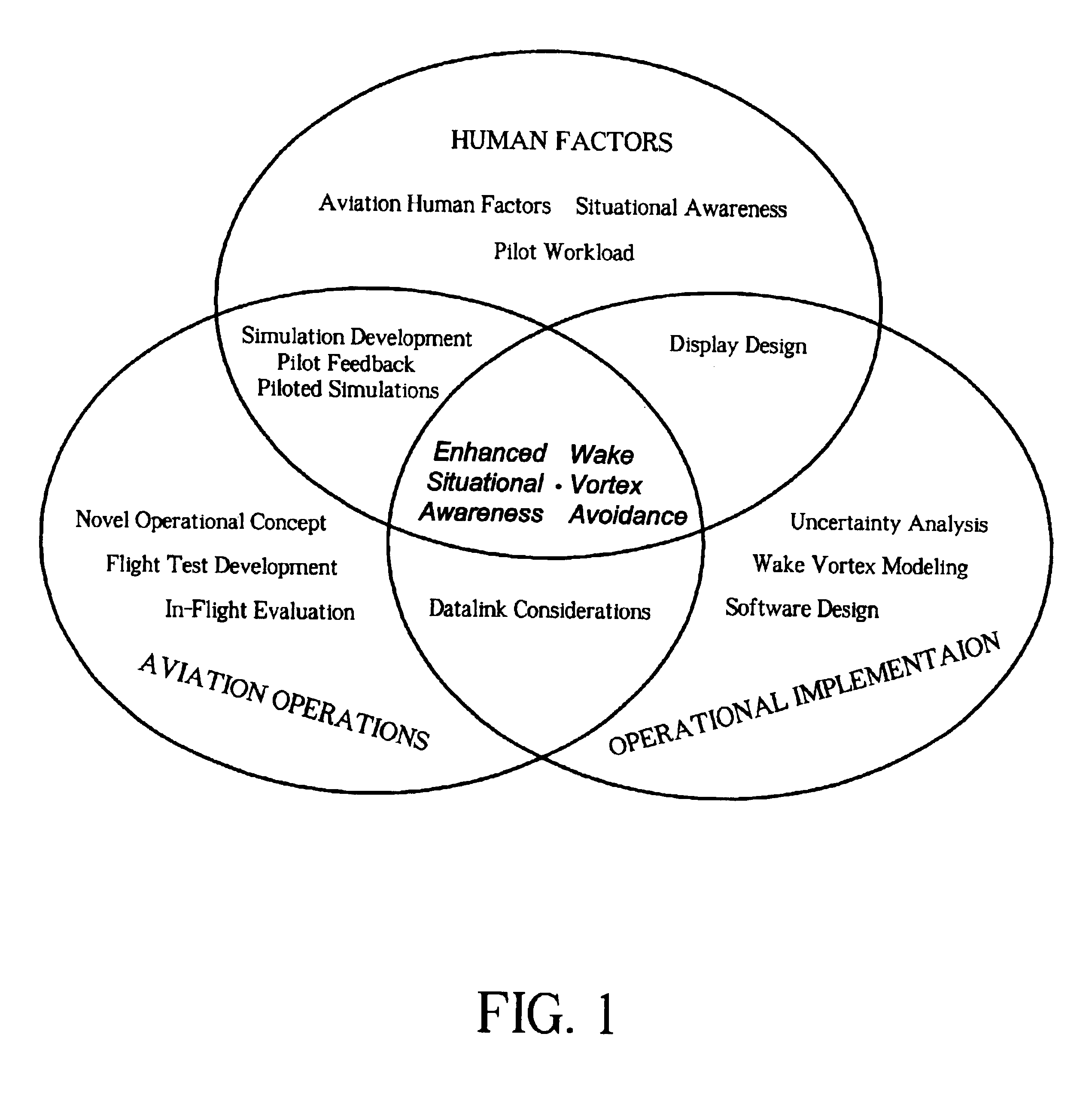
[0019]It is therefore a primary goal of the present invention to provide interested parties, e.g., flight crew, ground vehicle crew, ATC, etc. with a real-time prediction and realistic visualization of the location and movement of the wake turbulence of neighboring aircraft relative to the position and movement of oneself and / or of neighboring vehicles. This goal is achieved in a wake vortex avoidance system integrating the dynamic wake prediction and visualization methods and architecture disclosed herein.
[0020]According to the principles of the present invention, the system obtains in real time readily available aircraft and atmospheric data from ADS-B message and onboard instrumentation, such as INS and air data computers. Based on essential information extracted from these data, the system constructs a relatively simple wake model. The system predicts the location and movement of the wake based on the wake model and correspondingly determines the uncertainty in the wake prediction. This uncertainty is added to the wake prediction to form the wake hazard zone, which comprises a plurality of “wake planes” each moving independently from the others. The goal of the system is to keep the uncertainty to a minimum, thereby enhancing the accuracy of the wake prediction. The wake prediction, including the wake hazard zone (no fly zone), is communicated in real time directly to a user, such as a pilot, by rendering a realistic visual representation, preferably three-dimensional (3-D), of a neighboring aircraft as well as its wake.
[0021]Operational evaluation and flight tests demonstrated that the system accurately maps the no fly zone that wholly contains the dynamic, invisible wake hazard, enables pilots to view potential wake vortex encounters in an effective, reliable manner, and makes it possible to have safe separation distances between aircraft consistently smaller than those currently mandated by the FAA. While the current minimum separation distance standards ensure safety, they have an adverse effect on airport capacity. In addition to enhancing situational awareness of the pilots, the system helps alleviating airport capacity problems without compromising safety.
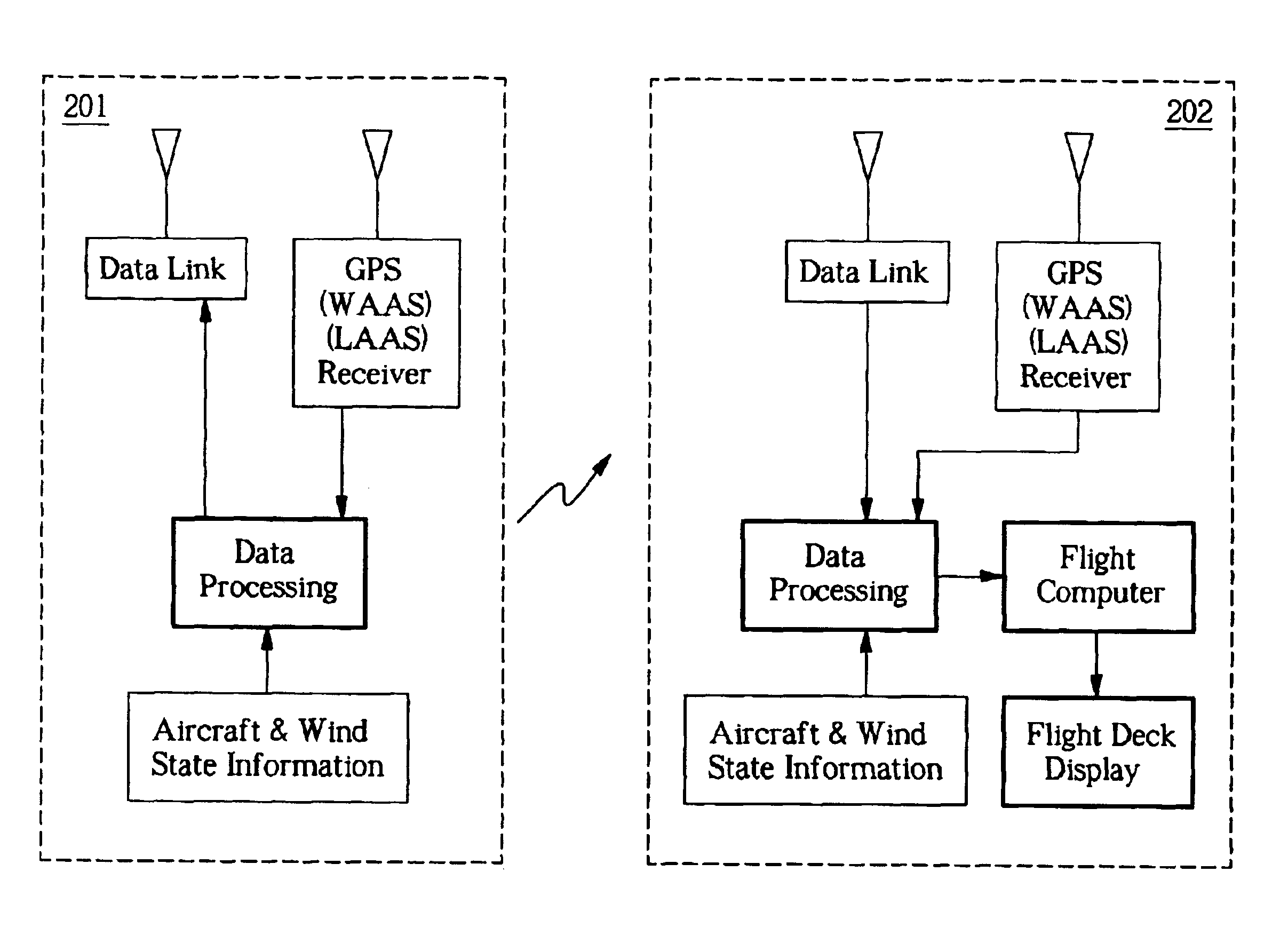
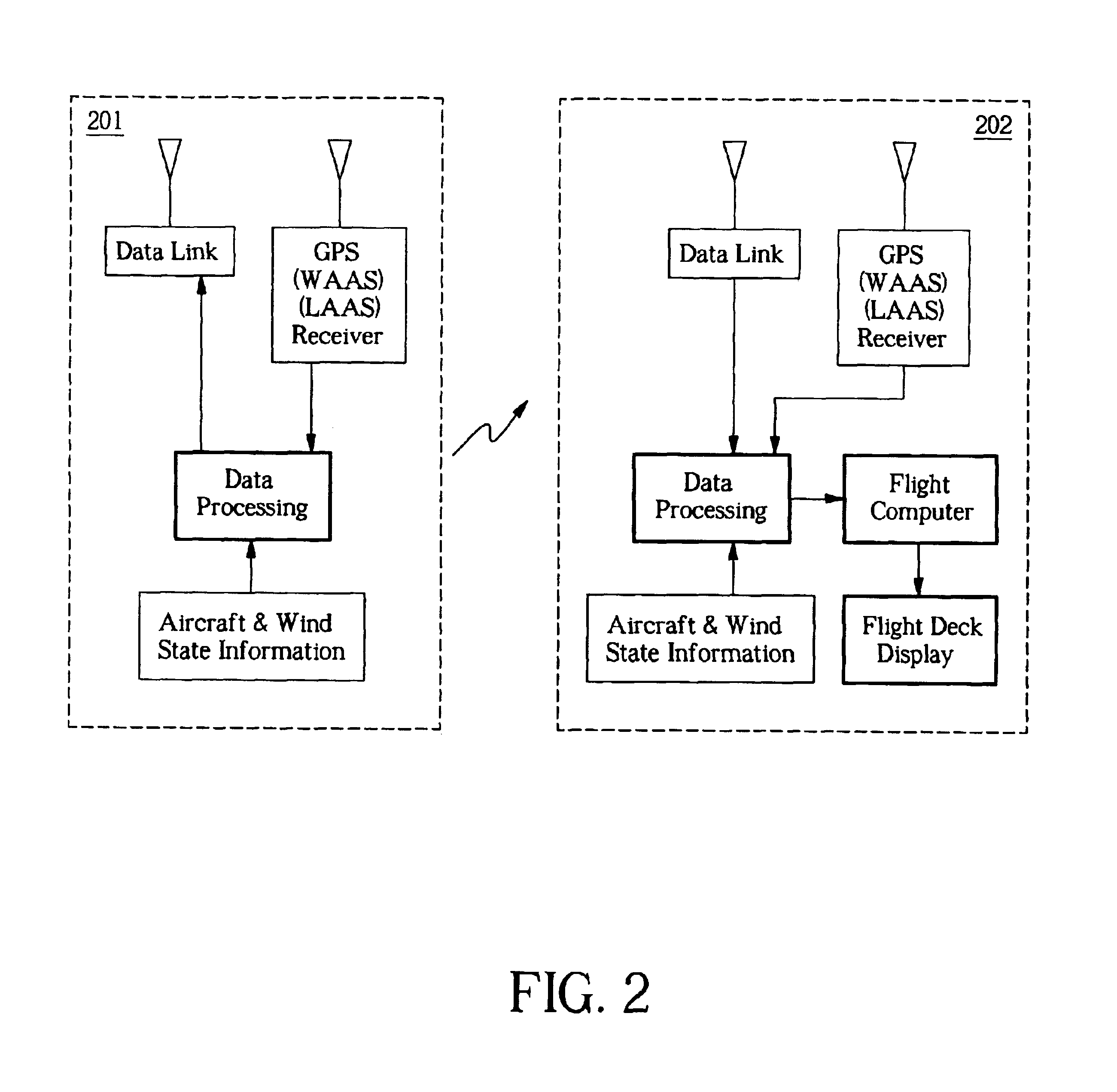
[0022]The wake vortex avoidance system according to the present invention is self-contained, requires no ground-based components, and can be implemented relatively inexpensively for either or both ground-based and airborne applications. Enabling technologies include GPS and ADS-B for determining and broadcasting (air-air / air-ground) the location and position of aircraft. The System comprises a broadcast function and a receive function. The broadcast function delivers in real-time information on the wake and the wake generating aircraft and comprises a GPS receiver and associated components for processing and utilizing the GPS signal; means for assessing and processing the aircraft (ownship) state information including TAS, position, and ground speed; means for calculating wind data; and a data link transceiver and associated components for formulating a broadcast. The receive function receives the broadcast and processes the data to construct a realistic visualization of the wake hazard prediction and comprises a data link transceiver and associated components for receiving and processing the broadcast; a GPS receiver and associated components for processing and utilizing the GPS signal; means for assessing and processing the ownship state information; means for calculating wind data; data processing and flight computer for collecting applicable data and constructing the wake hazard prediction; and a wake visualization device such as a 3-D graphical display.

Problems solved by technology

While the current minimum separation distance standards ensure safety, they have an adverse effect on airport capacity.

Method used


Image

  • Dynamic wake prediction and visualization with uncertainty analysis
  • Dynamic wake prediction and visualization with uncertainty analysis
  • Dynamic wake prediction and visualization with uncertainty analysis

Examples


Embodiment Construction

Wake Turbulence and Current Separation Standards

[0048]Airborne wake turbulence is the turbulence that a wing creates in the process of producing lift, which is the result of the difference in air pressure between the upper and lower surface of the wing. A heavier airplane needs more lift, so a heavier airplane generates larger wake turbulence. Interest in the wake turbulence phenomenon increased substantially with the introduction of the larger so called wide-body turbojet aircraft in the late 1960s. Through flight tests, the FAA observed the following:[0049]1) The strength of the wake turbulence is governed by the weight, speed and wingspan of the generating aircraft.[0050]2) The greatest strength occurs when the generating aircraft is heavy, at slow speed with a clean wing configuration.[0051]3) The wake was observed to move down initially and then level off. It was never encountered at the same flight level as the generating aircraft nor more than 900 feet below the generating ai...


PUM


Abstract

A dynamic wake avoidance system utilizes aircraft and atmospheric parameters readily available in flight to model and predict airborne wake vortices in real time. A novel combination of algorithms allows for a relatively simple yet robust wake model to be constructed based on information extracted from a broadcast. The system predicts the location and movement of the wake based on the nominal wake model and correspondingly performs an uncertainty analysis on the wake model to determine a wake hazard zone (no fly zone), which comprises a plurality of “wake planes,” each moving independently from another. The system selectively adjusts dimensions of each wake plane to minimize spatial and temporal uncertainty, thereby ensuring that the actual wake is within the wake hazard zone. The predicted wake hazard zone is communicated in real time directly to a user via a realistic visual representation. In an example, the wake hazard zone is visualized on a 3-D flight deck display to enable a pilot to visualize or “see” a neighboring aircraft as well as its wake. The system substantially enhances the pilot's situational awareness and allows for a further safe decrease in spacing, which could alleviate airport and airspace congestion.

Description

CROSS-REFERENCE TO RELATED APPLICATION[0001]This application claims the benefit of a provisional patent application No. 60 / 381,464, filed May 17, 2002, the content of which is hereby incorporated herein by reference.STATEMENT REGARDING FEDERALLY SPONSORED RESEARCH OR DEVELOPMENT[0002]This invention was supported in part by Federal Aviation Administration (FAA) Grant No. 95-G-005. The U.S. Government may have certain rights in this invention.BACKGROUND OF THE INVENTION[0003]1. Field of the Invention[0004]The present invention relates generally to wake vortex avoidance, and, more particularly, to a self-contained, dynamic wake prediction and visualization system and architecture capable of accurately predicting wake vortices / turbulence and visualizing, via realistic representation, a no fly zone with the certainty that the wake hazard is wholly contained therein.[0005]2. NomenclatureADS-BAutomatic Dependent Surveillance BroadcastAIMAeronautical Information ManualATAAir Transport Assoc...

Claims


Application Information

Patent Timeline
Patent Type & Authority Patents(United States)
IPC IPC(8): B64D43/00
CPCB64D43/00G01C23/005
Inventor HOLFORTY, WENDY L.POWELL, J. DAVID
Owner NAT AERONAUTICS & SPACE ADMINISTATION THE UNITED STATES GOVERNMENT AS REPRESENTED BY THE ADMINISTATION OF THE THE
Learn More