Eureka AIR delivers breakthrough ideas for toughest innovation challenges, trusted by R&D personnel around the world.

RFID tag wide bandwidth logarithmic spiral antenna method and system

Active Publication Date: 2005-11-08
SEMICON COMPONENTS IND LLC
View PDF4 Cites 52 Cited by
  • Summary
  • Abstract
  • Description
  • Claims
  • Application Information

AI Technical Summary

Benefits of technology

[0016]Typically, the presence of the tag is sensed by noting the i

Problems solved by technology

Therefore passive transponders require higher signal strength, while active transponders require much less signal strength, but at the cost of a power source.
A company named Intermec, sells an expensive 915 MHz tag system.
Moreover, the partial spiral limits bandwidth, which is desired in this patent, and the spaced ground plane adds cost.
The '342 patent uses a distorted spiral to gain a larger antenna in a button sized package and also uses a loading bar and stubs to match impedances, but adds complexity and cost, but does not appear to extend the useable range beyond the above mentioned thirty inches.
Clearly this antenna is not suited for RFID applications.

Method used


Image

  • RFID tag wide bandwidth logarithmic spiral antenna method and system
  • RFID tag wide bandwidth logarithmic spiral antenna method and system
  • RFID tag wide bandwidth logarithmic spiral antenna method and system

Examples


Embodiment Construction

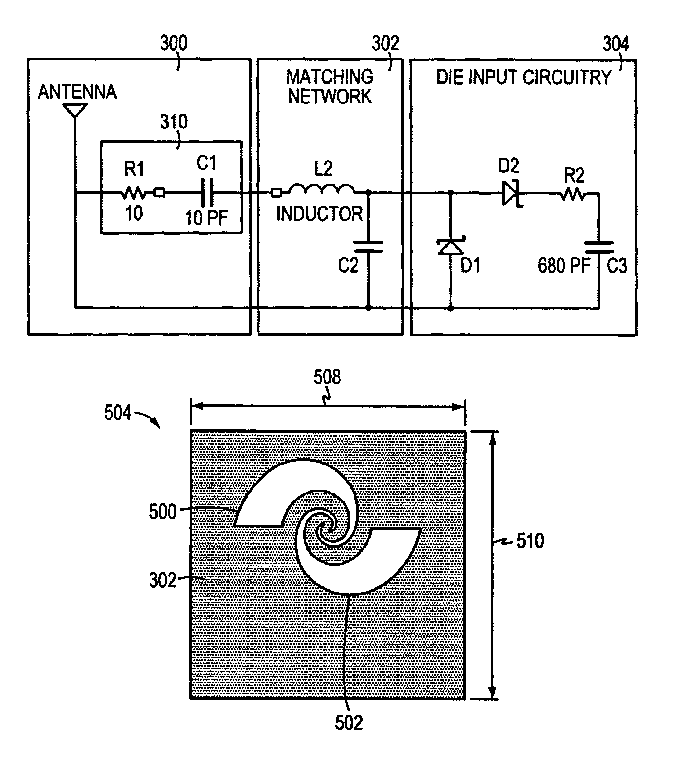
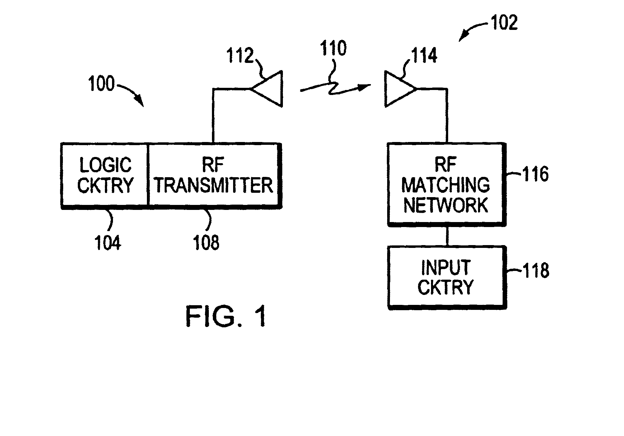
[0026]FIG. 1 is a basic block diagram of an illustrative RFID tag system. Here an interrogation station 100 generates an RF signal 108, usually a pulse signal generated by the logic circuit 104, that is transmitted 110 via an antenna 112 to a tag system 102. The RF pulse is received via an antenna 114 and an RF impedance matching circuit 116 as is known in the art, and, an input circuit 118. If the RF signal is strong enough, the input circuitry rectifies the RF signal and charges a capacitor that is used to power the tag system when the RF signal is low. As is known in the art, the tag circuit presents a load to the RF transmitter causing the RF transmitter power to increase in the presence of a tag. In one embodiment, as known in the art, the driving RF voltage signal is stepped up. That increase may be sensed by the logic circuitry 104 to indicate the presence of the tag. Other known techniques may used to generate and detect a tag.

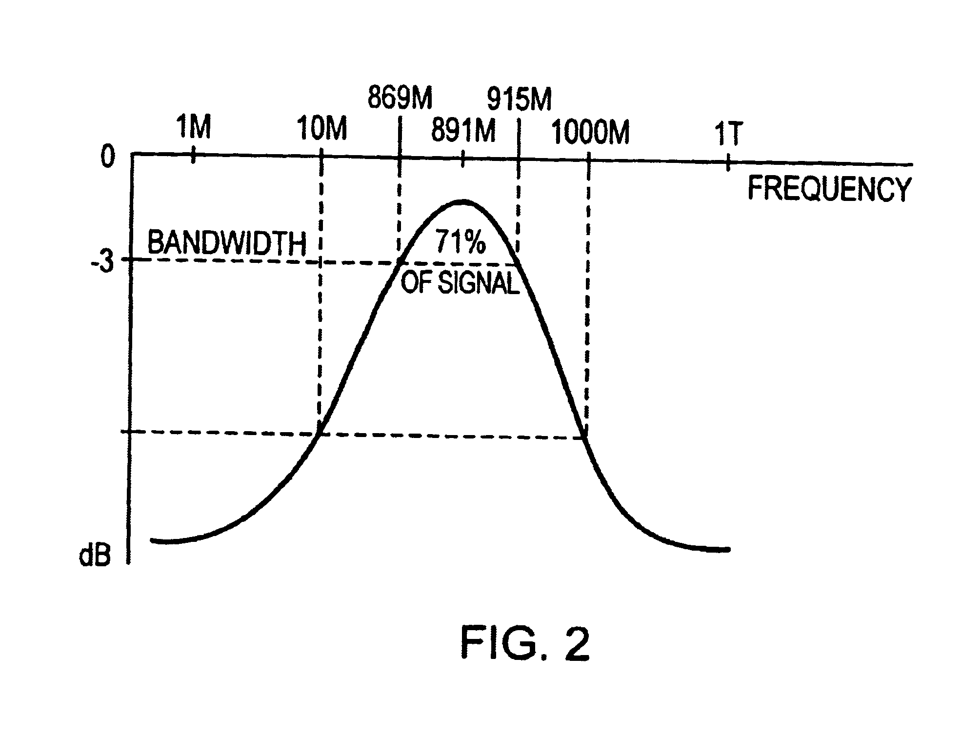
[0027]FIG. 2 shows a frequency response for a tr...


PUM


Abstract

A radio frequency identification (RFID) tag antenna system includes a planar two arm logarithmic spiral antenna with a suitably small form factor. There are two arms are of conductive foils or etched copper plating on a substrate the extend outwardly from a center in a logarithmic fashion. The two arms are identical to each other but rotated in the plane by 180 degrees. The arms also grow proportionally in width as they extend outward, but at any given distance from the center the width of both arms are equal to each other and, preferably, equal to the spaces between the arms. An impedance matching network receives the RF signal received by the dual spiral antenna and feed the RF signal to an electronic circuit that rectifies and multiplies the signal to form a DC signal that charges a capacitor. The electronics may be built onto the same substrate as the planar antenna, but preferably, the electronic circuit is built onto a second substrate is mounted, making appropriate electrical connections, to the antenna bearing substrate.

Description

CROSS-REFERENCE TO RELATED APPLICATIONS[0001]The present application claims the benefit of U.S. Provisional Patent Application Ser. No. 60 / 412,526, which was filed on Sep. 20, 2002, of common title and inventorship with the present applications, and which application is hereby incorporated herein by reference.BACKGROUND OF THE INVENTION[0002]1. Field of the Invention[0003]The present invention relates to radio frequency identification (RFID), and more particularly to wide bandwidth spiral antennas, radio frequency (R) transponder tag circuitry and impedance matching networks.[0004]2. Background Information[0005]Radio frequency identification (RFID) is well known using 125 KHz and 13.56 MHz for passive and active transponders, respectively. A passive transponder accepts power from the received signal and returns an identification signal. Active transponders contain a power source and need not be powered from the received signal. Therefore passive transponders require higher signal st...

Claims


Application Information

Patent Timeline
IPC IPC(8): H01Q1/36G06KG06K17/00G06K19/07G06K19/077H01Q9/27H01Q11/08H01Q21/00H01Q23/00H04B1/59
CPCG06K19/07749H01Q11/10H01Q9/27H01Q1/2208H01Q11/08G06K19/07G06K17/00
Inventor ZUK, PHILIP C.ROBERTS, RAYMOND A.VOGT, III, JOHN V.
Owner SEMICON COMPONENTS IND LLC
Why Eureka
Eureka Blog
Learn More