
Cathodic test lead and pig monitoring system

Inactive Publication Date: 2005-11-15
STAR TRAK PIGGING TECH
View PDF13 Cites 86 Cited by
  • Summary
  • Abstract
  • Description
  • Claims
  • Application Information

AI Technical Summary

Benefits of technology

[0023]A significant advantage of the present invention is that the cost of monitoring pipeline operations is significantly reduced, while also reducing the risk of accidents involved with pipeline personnel manually checking operations at monitoring stations.
[0024]A related advantage of the invention is that each of the components of the system is readily available, so a highly reliable and cost effective monitoring system is obtained.

Problems solved by technology

Over a period of time, contaminates or residues accumulate on the inner walls of the pipe, thereby reducing pipeline flow efficiency.
Because pigs are susceptible to becoming obstructed within the pipe, knowing the location of the pig is critical.
However, this method is expensive since crews of technicians stationed at points along the route of the pipeline are required to listen for the pig.
Low frequency electromagnetic transmitters have been attached to the pig, but these require on-board power, which is susceptible to failure or power loss.
Using the above techniques, receiving a locating signal from the pig was often unreliable.
Although these mechanisms provide location data, the intrusion created for the mechanical signaling device undesirably affect the integrity of the pipeline since the entire system must be shut down for maintenance of the pig passage signaling device.
These techniques have significant disadvantages in that they use significant personnel to perform the search and hopefully locate the pig.
All forms of pigs are susceptible to becoming lost or obstructed during their travel from one section of the pipeline to another.
However, the distance between magnetic passage indicators may be as great as several miles, and the expense of locating the lost pig includes high personnel costs and long delays, leading to lost production.
After detection of corrosion, it has been a problem to accurately identify, within a few feet, the location of the pig along the pipeline when the corrosion signal was obtained.
However, odometers may “skid”, causing erroneous information.
In addition to concerns regarding pitting or corrosion of the internal pipe wall, corrosion also may occur on the outer wall or skin of the pipeline.
Due to insufficient wrapping protection, the integrity of the cathodic protection at sections along the pipeline route may be susceptible to corrosion.
Contractors digging close to pipelines may inadvertently damage a pipeline.
Damage to the pipe protective wrapping often leads to corrosion, which is the major cause of pipeline leaks or blowouts.
Also, attacks to the pipeline by terrorists or illegal tapping of the pipe contents can cause severe disruption to the pipeline system.
Obtaining monthly data cathodic test lead stations is labor intensive, and prevents technicians from performing other pipeline duties.
Moreover, this labor intensive staff typically experience long driving hours under variable weather conditions.
Pipeline operators recognize that many driving accidents occur in the pipeline industry because of the need to periodically monitor the cathodic test lead stations.

Method used


Image

  • Cathodic test lead and pig monitoring system
  • Cathodic test lead and pig monitoring system
  • Cathodic test lead and pig monitoring system

Examples


Embodiment Construction

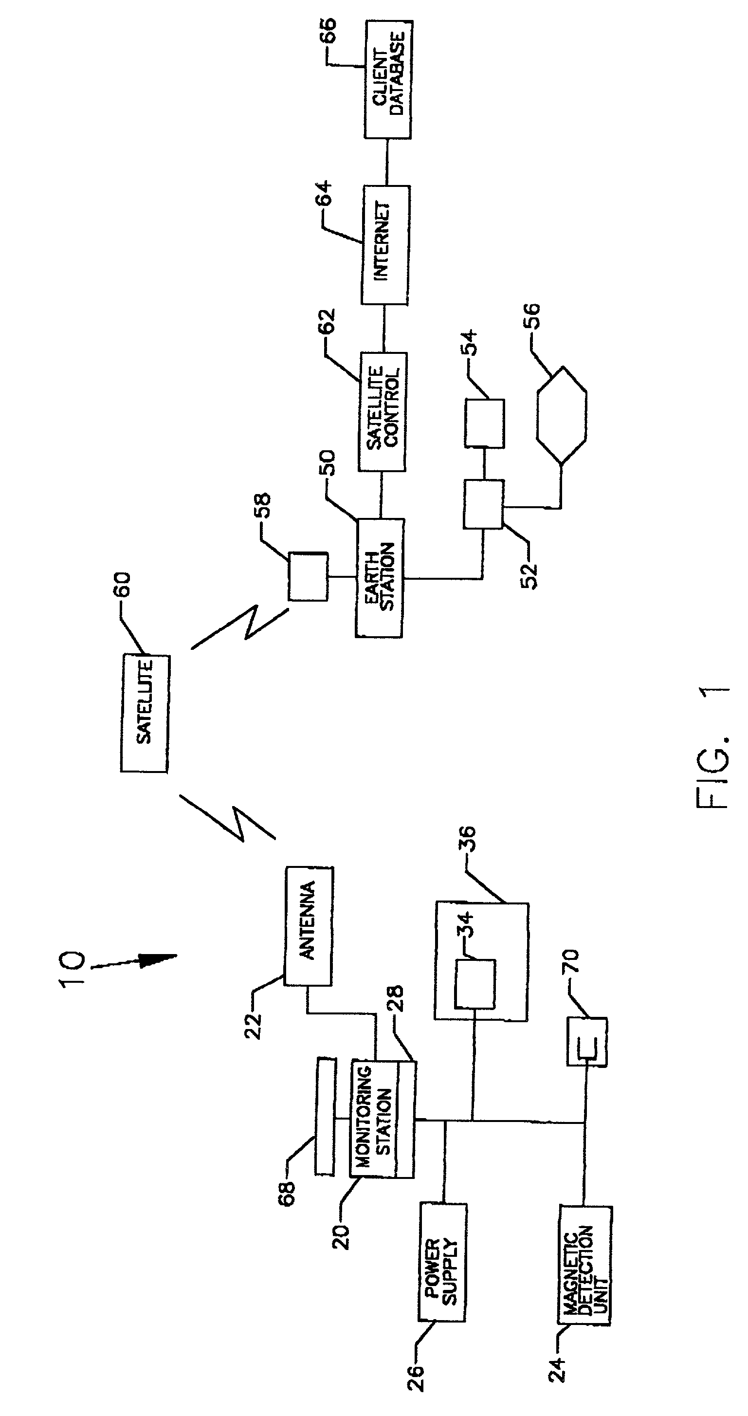
[0033]FIG. 1 illustrates a pipeline monitoring system 10 according to a preferred embodiment of the invention, As shown in FIG. 3, the pipeline P being monitored may include a plurality of pipe sections which are land based and underwater. The wide variety of environmental conditions which the pipeline may be exposed are known to those skilled in the art.

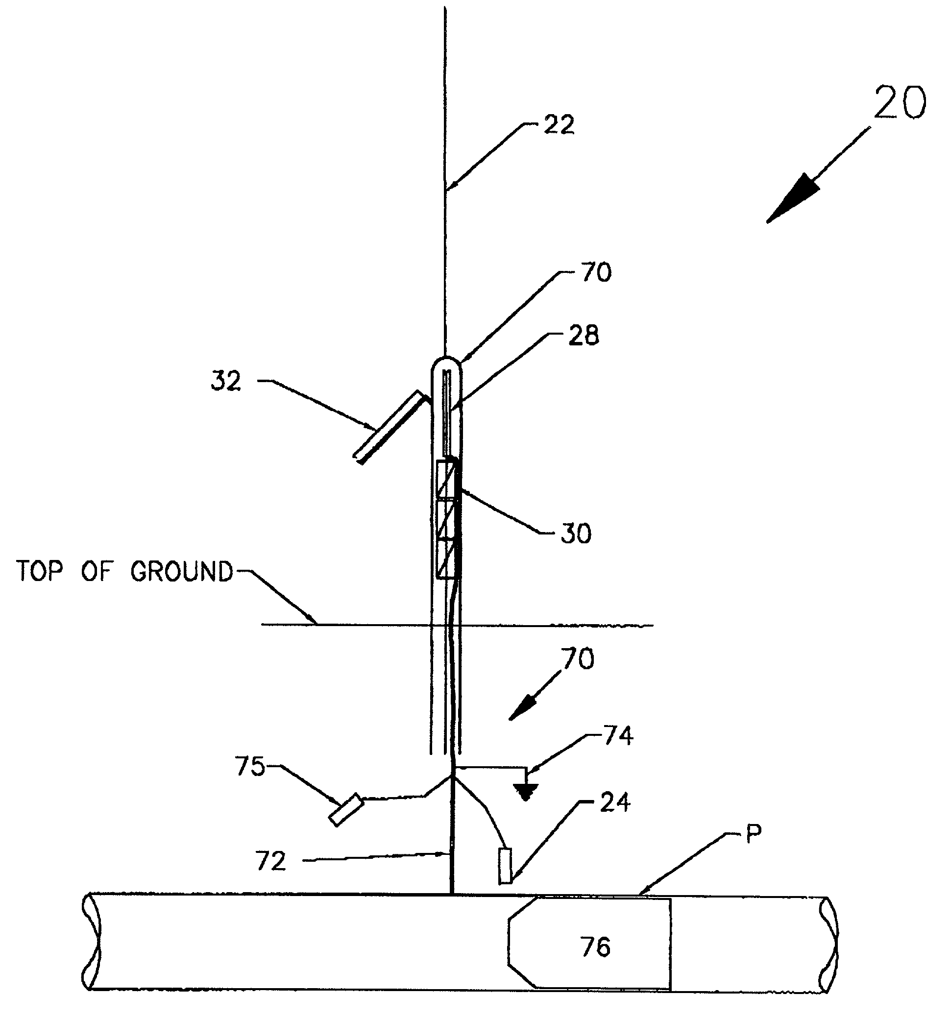
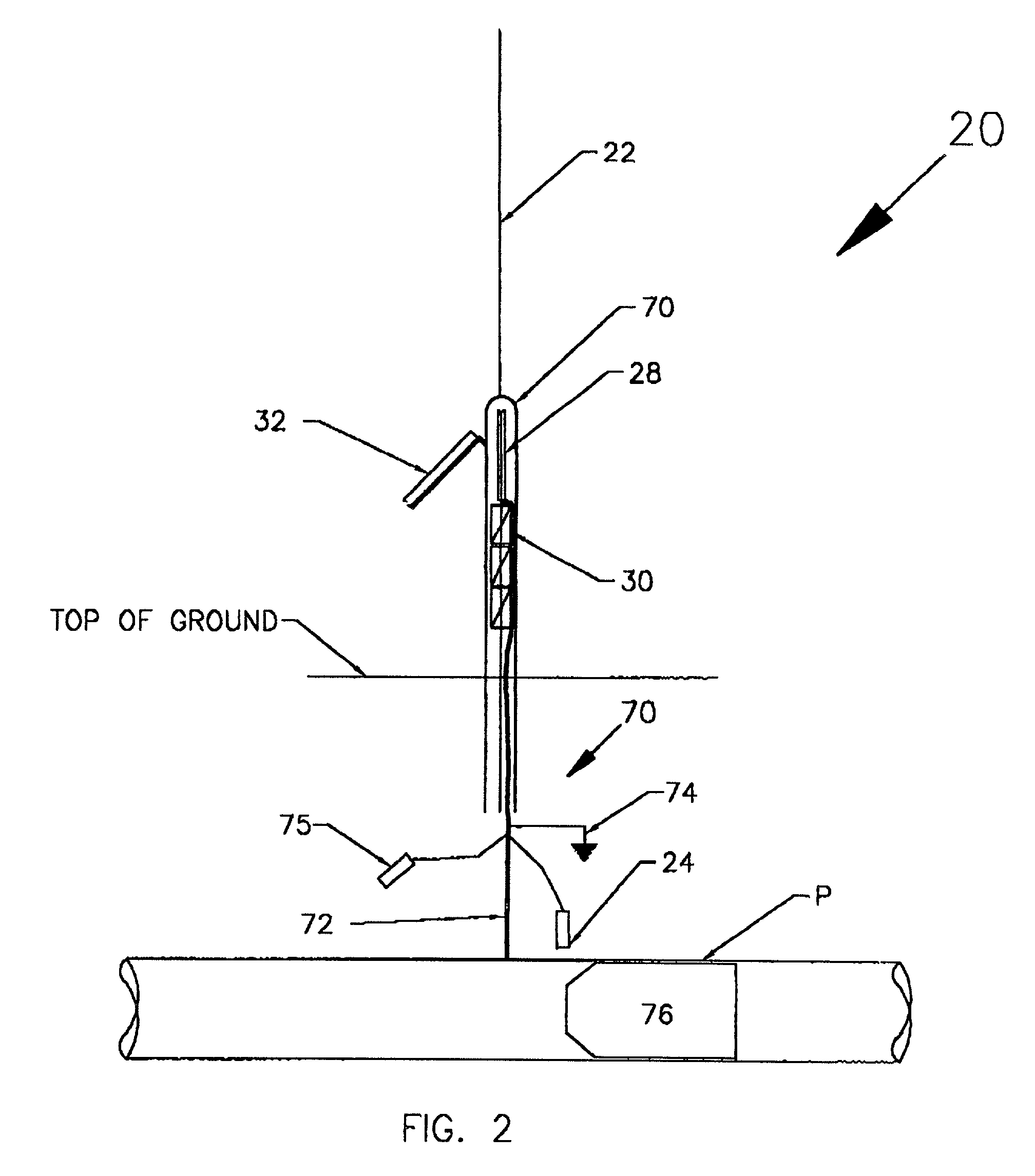
[0034]Positioned along the pipeline are plurality of monitoring stations 20, with one such station being shown in FIG. 1. The number of monitoring stations will depend on the length of the pipeline being monitored, and literally hundreds or thousands of monitoring stations may be monitored according to the system of the present invention. Each monitoring stations communicates with a central monitoring facility 50, as discussed below.

[0035]Each monitoring station 20 serves as a data collection unit. A data transmission unit 22, which may include an antenna and related communication circuitry such as that offered by Quake Global Commu...


PUM


Abstract

A pipeline monitoring system includes a series of monitoring stations (20), each having a computer (68), magnetic pig position detector (24), one or more input / output modules (90) and communications module (86). The communications module is operable to transmit data over a communications network from a remotely located monitoring stations (20) to a central monitoring facility (50). Commands transmitted from the central monitoring facility or events generated by the passage of a magnetic pig cause the monitoring station to automatically perform selected processes. The central monitoring facility may also use preprogrammed commands to effect reporting at pre-selected times and dates, and may forward pipe / soil potentials or pipeline damage signals to the central monitoring facility.

Description

FIELD OF THE INVENTION[0001]The present invention relates to computer controlled pipeline monitoring and, more specifically, to multiple monitoring stations which may each include cathodic test leads for detecting pipe / soil potentials, a pipeline pig detector, a pipe damage detector, and a satellite communications module for communication with a central monitoring facility.BACKGROUND OF THE INVENTION[0002]Pipelines are utilized throughout the world to transport a variety of liquid products, including oil, petroleum products, natural gas, and chemicals. Over a period of time, contaminates or residues accumulate on the inner walls of the pipe, thereby reducing pipeline flow efficiency. In order to extract the build up, an internal traveler known as a pig is propelled through the pipe. Besides cleaning the interior walls of the pipe, pigs are useful for pipe gauging, line fill and de-watering, product separation, leak detection, and corrosion, internal thermal, and / or video surveys.[00...

Claims


Application Information

Patent Timeline
IPC IPC(8): G08C19/16G08C19/22H04Q9/00F16L55/48
CPCF16L55/48
Inventor CASEY, ERNEST D.CASEY, IAN D.
Owner STAR TRAK PIGGING TECH
Features
  • Generate Ideas
  • Intellectual Property
  • Life Sciences
  • Materials
  • Tech Scout
  • Unparalleled Data Quality
  • Higher Quality Content
  • 60% Fewer Hallucinations
Learn More