Radiological imaging apparatus and radiological imaging method
a radiological imaging and apparatus technology, applied in the direction of tomography, material analysis using wave/particle radiation, instruments, etc., can solve the problems of complex apparatus configuration of radiological imaging apparatuses, inability to obtain the angle of incidence upon the detector, and inability to identify the detailed position of the focus, etc., to achieve the effect of simplifying the configuration of radiological imaging apparatus
- Summary
- Abstract
- Description
- Claims
- Application Information
AI Technical Summary
Benefits of technology
Problems solved by technology
Method used
Image
Examples
embodiment 1
(Embodiment 1)
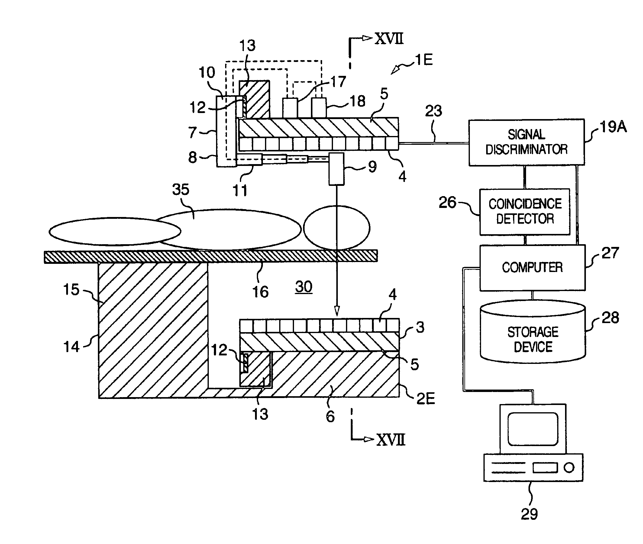
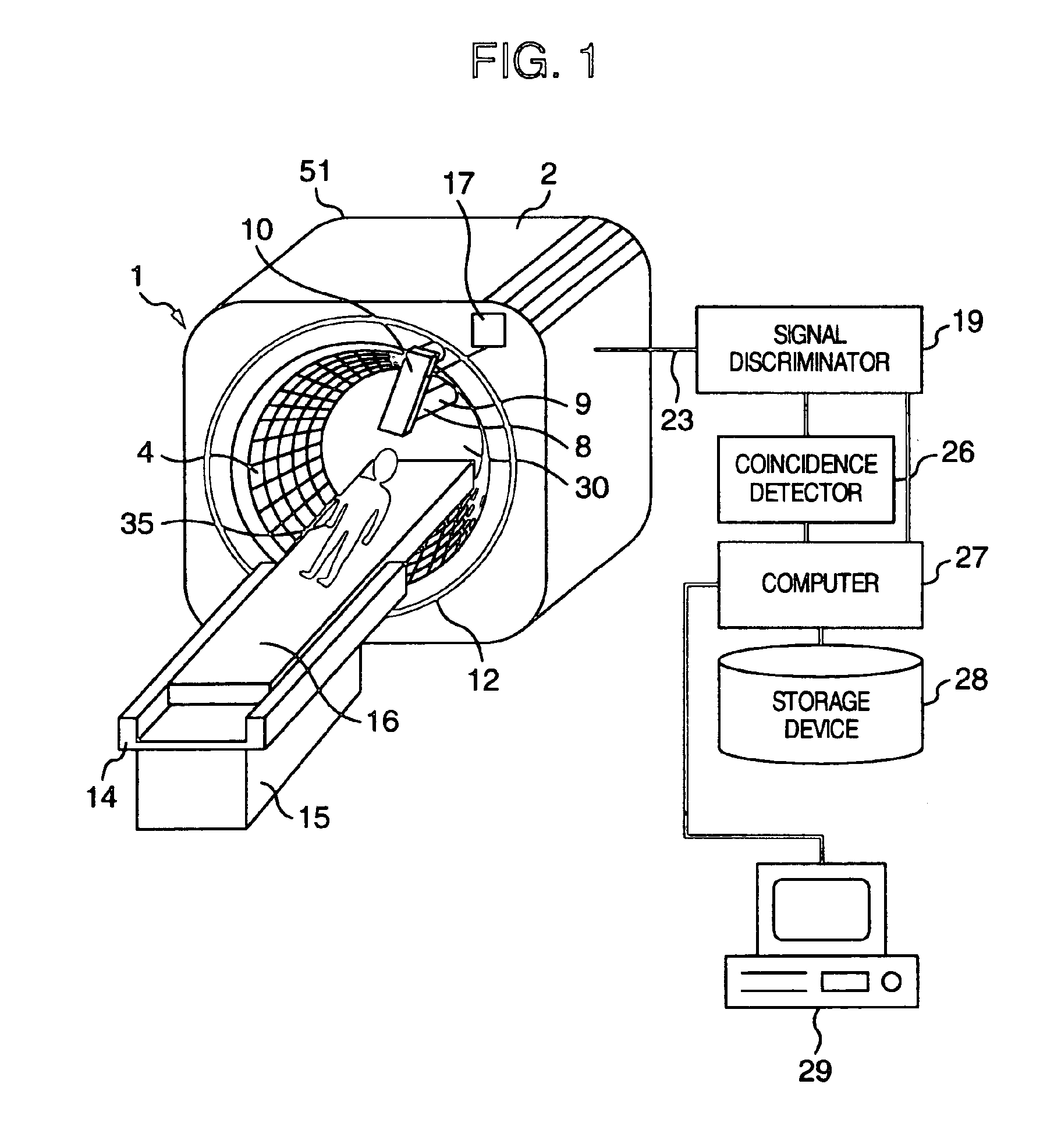
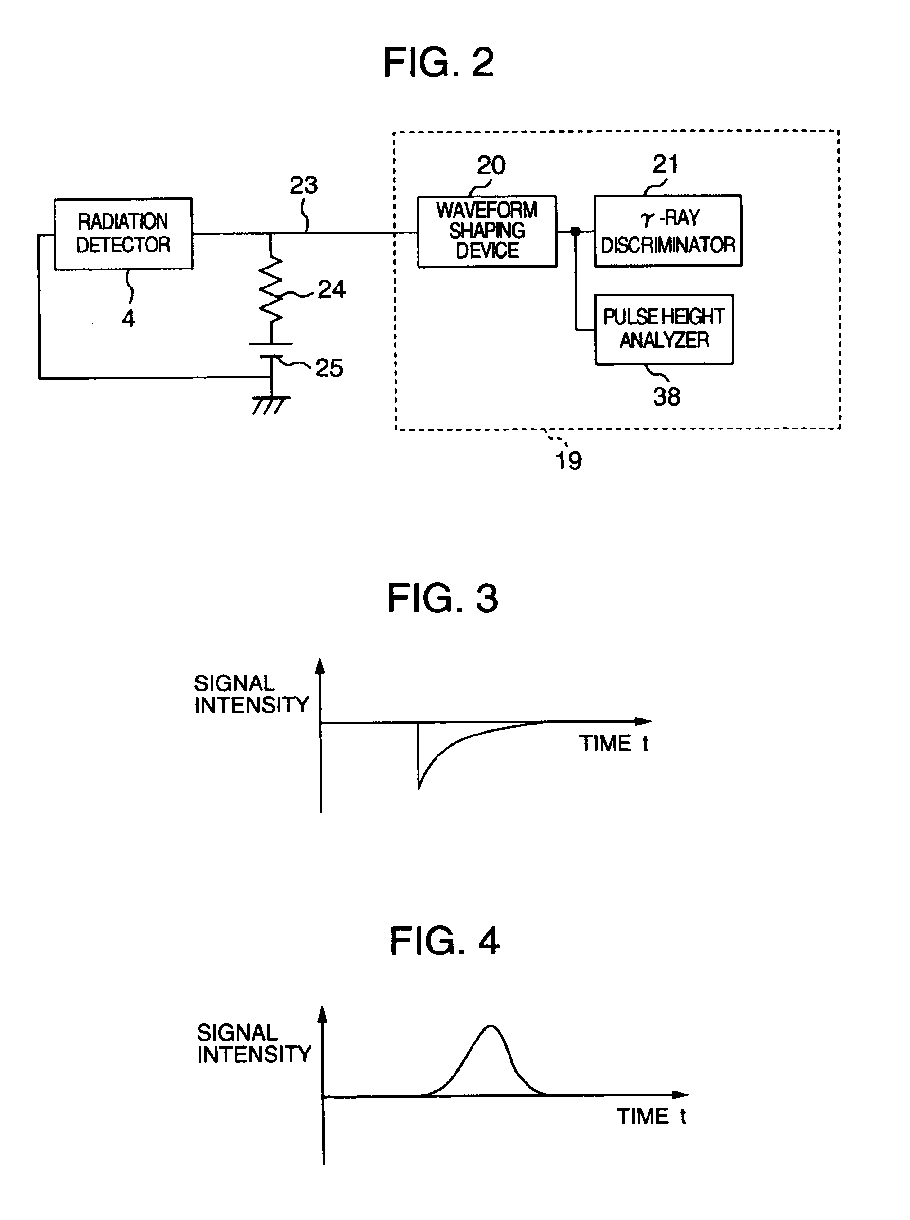
[0039]With reference now to FIG. 1 and FIG. 2, a radiological imaging apparatus which is a preferred embodiment of the present invention will be explained below. A radiological imaging apparatus 1 of this embodiment is provided with an image pickup apparatus 2, an examinee holding apparatus 14, a signal discriminator 19, a coincidence detector 26, a storage device 28, a computer 27 and a display device 29. The examinee holding apparatus 14 includes a support 15 and a bed installed on top of the support 15 in a manner movable in a longitudinal direction. The image pickup apparatus 2 includes radiation detectors 4, a casing 15 provided with a through hole section 30, an X-ray source apparatus 8, a guide rail 12 and a drive controller 17. The image pickup apparatus 2 is installed in a direction perpendicular to the longitudinal direction of the bed 16. The radiation detector 4 is a semiconductor radiation detector. Many radiation detectors 4 (10000 in total) are set in th...
embodiment 2
(Embodiment 2)
[0070]A radiological imaging apparatus according to another embodiment of the present invention will be explained. Though not shown, the configuration of this embodiment uses a signal discriminator 19A shown in FIG. 8 instead of the signal discriminator 19 in the configuration in FIG. 1. The signal discriminator 19A can also be used as a substitute for the signal discriminator 19 in Embodiment 4, which will be described later. The signal discriminator 19A has a configuration with a changeover switch 31 added to the aforementioned signal discriminator 19 and the pulse height analyzer 38 replaced by a signal processor 22. The signal discriminator 19A is provided with a waveform shaping device 20, a γ-ray discriminator 21 and the signal processor 22 for calculating the intensity of X-rays. The signal processor 22 is provided with an integrator (not shown). The changeover switch 31 includes a movable terminal 32 and fixed terminals 33 and 34. Wiring 23 is connected to the ...
embodiment 3
(Embodiment 3)
[0079]A radiological imaging apparatus according to another embodiment of the present invention will be explained using FIG. 10. This embodiment shows an example of conducting X-ray computed tomographic inspection and PET inspection using one image pickup apparatus 2A. The radiological imaging apparatus 1A of this embodiment is provided with a radiation detector 4A connected to a signal processor 22 via wiring 23B and a radiation detector 4B connected to a signal discriminator 19B via wiring 23A. The radiation detector 4A and radiation detector 4B are semiconductor radiation detectors as in the case of the radiation detector 4. The radiation detector 4A and radiation detector 4B are placed alternately in the circumferential direction of the through hole section 30 of the image pickup apparatus 2A. The radiation detector 4A and radiation detector 4B need not always be placed alternately, but the ratio of their arrangement can be changed if necessary. The signal discrimi...
PUM
 Abstract
Description
Claims
Application Information
 - R&D
- Intellectual Property
- Life Sciences
- Materials
- Tech Scout
- Unparalleled Data Quality
- Higher Quality Content
- 60% Fewer Hallucinations
Browse by: Latest US Patents, China's latest patents, Technical Efficacy Thesaurus, Application Domain, Technology Topic, Popular Technical Reports.
© 2025 PatSnap. All rights reserved.Legal|Privacy policy|Modern Slavery Act Transparency Statement|Sitemap|About US| Contact US: help@patsnap.com


