Controlled oscillator circuitry for synthesizing high-frequency signals and associated method

a technology of controlled oscillator circuit and high-frequency signal, which is applied in the direction of pulse automatic control, modulation, transmission, etc., can solve the problems of mixing undesired channels, impure frequency sources creating interference in neighboring channels, and design of pll synthesizer solutions

Inactive Publication Date: 2005-11-15
SILICON LAB INC
View PDF92 Cites 13 Cited by
  • Summary
  • Abstract
  • Description
  • Claims
  • Application Information

AI Technical Summary

Benefits of technology

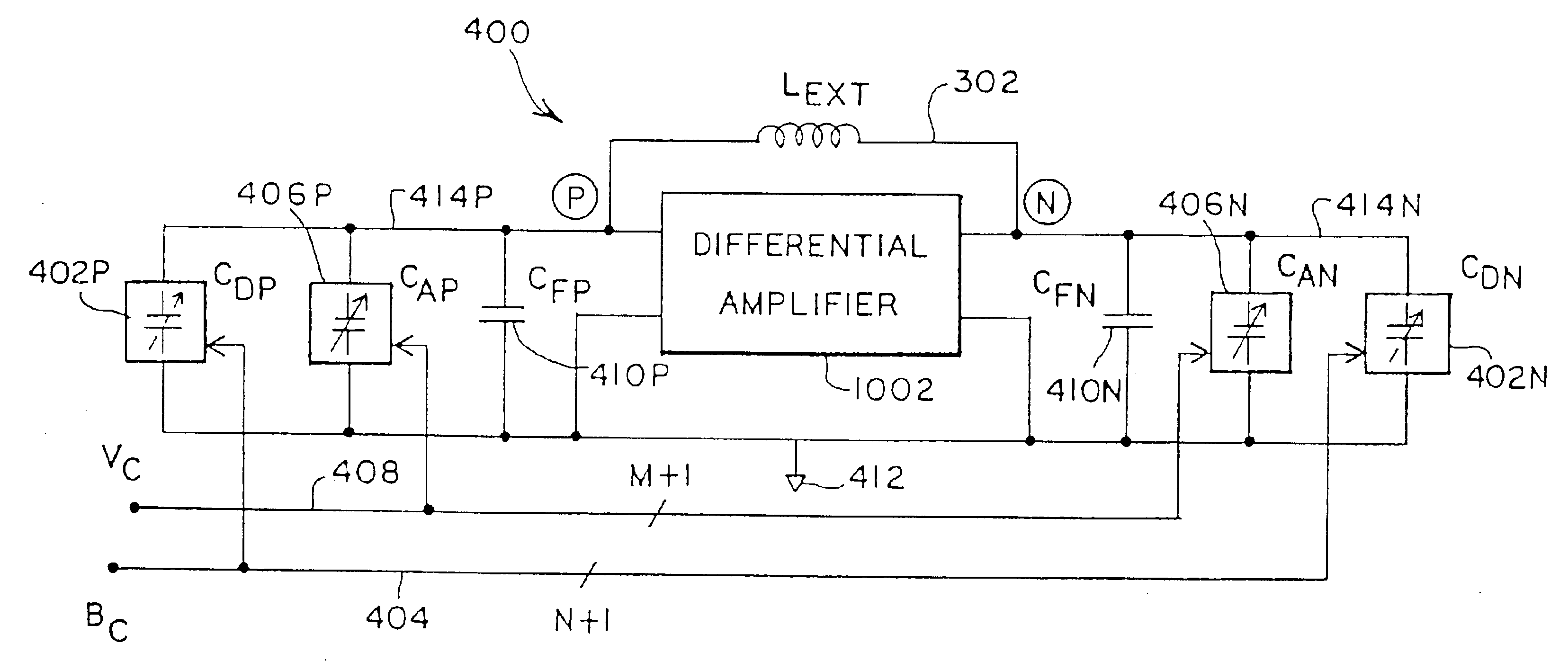
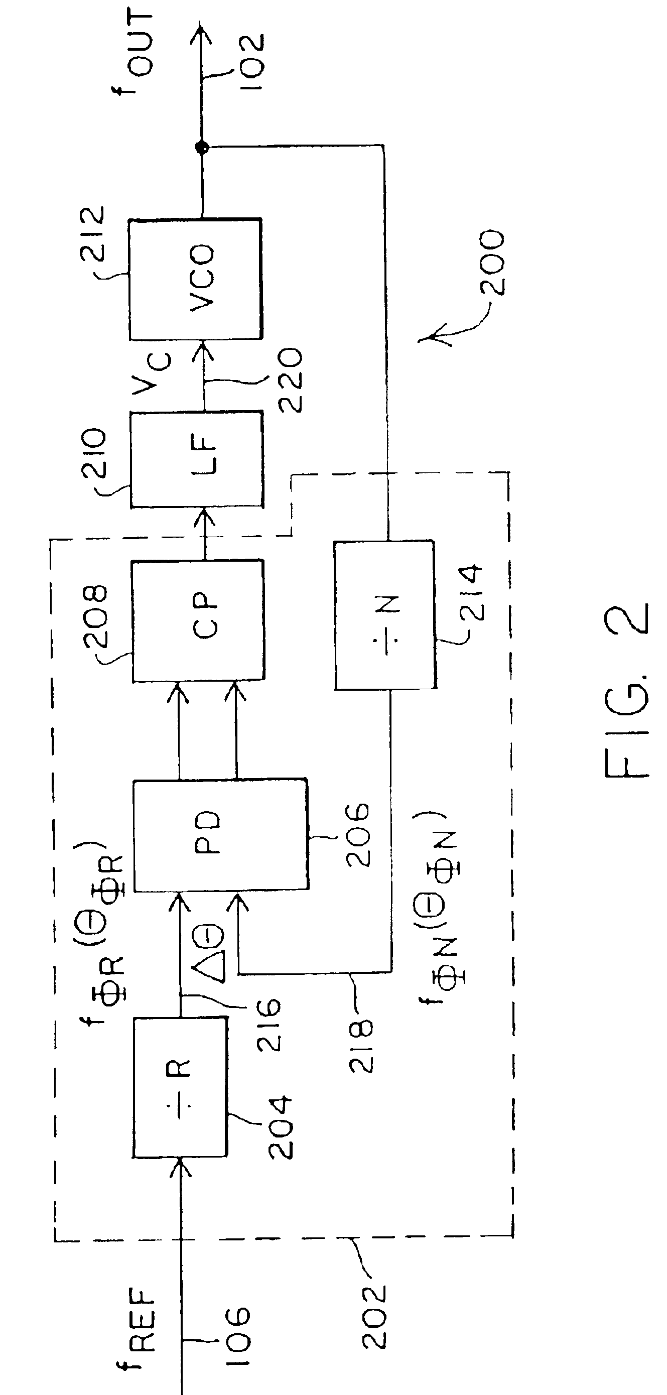
[0012]In accordance with the present invention, a method and apparatus for synthesizing high-frequency signals is disclosed that overcomes the integration problem associated with prior implementations and meets the demanding phase noise and other impurity requirements. The present invention achieves this advantageous result by implementing a phase-locked loop (PLL) frequency synthesizer with a variable capacitance voltage controlled oscillator (VCO) that includes a discretely variable capacitance in conjunction with a continuously variable capacitance. The discretely variable capacitance may provide coarse tuning adjustment of the variable capacitance to compensate for capacitor and inductor tolerances and to adjust the output frequency to be near the desired output frequency. The continuously variable capacitance may provide a fine tuning adjustment of the variable capacitance to focus the output frequency to match precisely the desired output frequency and to provide compensation for post-calibration drift of the PLL circuitry. The present invention avoids the need for a traditional varactor implementation in the VCO, for a traditional large capacitor component in the loop filter, and for component trimming during processing and thereby provides a high-frequency frequency synthesizer that may be fully integrated on a single chip except for an external inductor.

Problems solved by technology

For signal reception, impure frequency sources result in mixing of undesired channels into the desired channel signal.
For signal transmission, impure frequency sources create interference in neighboring channels.
The level of spectral purity required in cellular telephone applications makes the design of a PLL synthesizer solution and, in particular, the design of a VCO within a PLL synthesizer solution quite demanding.
Phase noise is undesired energy spread continuously in the vicinity of the output frequency, invariably possessing a higher power density at frequencies closer to the fundamental of the output frequency.
Phase noise is often the most damaging of the three to the spectral purity of the output frequency.
It is often the case that the series resistance of the inductor is the dominant loss mechanism in an LC tank oscillator, although other losses typically exist.
While it is highly desirable to integrate the VCO with the other components of the PLL onto a single integrated circuit for cost, size, power dissipation, and considerations, barriers to integration exist.
One of the more significant barriers is the lack of precision in the values of the inductors and capacitors used in the LC tank of the PLL.
This tolerance problem typically forces most PLL synthesizer implementations to modify the inductor or capacitor values during production, for example, by laser trimming.
Further complicating integration is the difficulty in integrating an inductor with a low series resistance and a capacitor with a reasonably high value and with low loss and low parasitic characteristics.
In integrating capacitance values, a significant problem is the high value of a typical loop filter (LF) capacitor component, which is often on the order of 1-10 μF.
Another significant problem is the absence of a variable capacitance (CX) component that possesses a highly-variable voltage-controlled capacitance that is not also a high loss component that causes phase noise.
However, such high- varactors require special processing and, therefore, have not been subject to integration with the rest of the PLL circuitry.
In short, although integration onto a single integrated circuit of a PLL implementation for synthesizing high-frequency signals is desirable for a commercial cellular phone application, integration has yet to be satisfactorily achieved.

Method used


Image

  • Controlled oscillator circuitry for synthesizing high-frequency signals and associated method
  • Controlled oscillator circuitry for synthesizing high-frequency signals and associated method
  • Controlled oscillator circuitry for synthesizing high-frequency signals and associated method

Examples


embodiment 1300

[0070]FIG. 13 is a diagram of an embodiment 1300 for achieving a dual band operation for VCO 612. The VCO 612 receives a voltage control (VC) signal 408 and provides an RF output (RFOUT) frequency 102. The external inductor (LEXT) 1306 may be used to determine a first RF output frequency RF1. If a second RF output frequency RF2 is desired, NMOS transistor 1304 may be turned on through the assertion of a high logic level on control node (CTRL) 1302. When this occurs, an additional inductor (LPAR) 1308 will be connected in parallel with the external inductor (LEXT) 1306. In this manner, the output frequency may be selectively centered in two desired bands of frequencies. As the inductance changes, the center frequency of oscillation of the LC tank with the VCO 612 will also change. This approach may also be used to implement any desired number of frequency bands by adding additional switches and inductances. Disadvantages to this approach include the large tolerances associated with m...

embodiment 1400

[0071]FIG. 14 is a block diagram of an alternative embodiment 1400 for achieving dual band operation for VCO 612. A second switch (SW) 1410 is used to select either a first VCO (VCO1) 612A or a second VCO (VCO2) 612B. A first external inductor (LRF1) 1416 may be selected so that the VCO1612A has an RF output (RF1) 1412 centered in a first desired frequency band. Similarly, a second external inductor (LRF2) 1418 may be selected so that the VCO2612B has an RF output (RF2) 1414 centered in a second desired frequency band. The selected frequency is connected through switch 1410 to provide the desired output frequency (fOUT) 102. Power to the non-used VCO 612A or 612B may be shut down, for example by starving the circuit of current from a current generator. This multiple VCO arrangement according to the present invention eliminates potential sources of phase noise by moving the switch (SW) 1410 outside of the LC tank. This approach may also be used to implement any desired number of freq...


PUM


Abstract

A method and apparatus for synthesizing high-frequency signals, such as wireless communication signals, includes a phase-locked loop (PLL) frequency synthesizer with a variable capacitance voltage controlled oscillator (VCO) that has a discretely variable capacitance in conjunction with a continuously variable capacitance. The discretely variable capacitance may provide coarse tuning adjustment of the variable capacitance to compensate for capacitor and inductor tolerances and to adjust the output frequency to be near the desired frequency output. The continuously variable capacitance may provide a fine tuning adjustment of the variable capacitance to focus the output frequency to match precisely the desired frequency output. During fine tuning adjustment, the PLL may be controlled by a plurality of analog control signals. The analog control signals may be derived by first generating a plurality of phase shifted signals from a divided version of the VCO output clock. Second, the phase differences between the plurality of phase shifted signals and a divided version of a reference clock may be detected and then converted to the analog control signals.

Description

[0001]This application is a continuation application of application Ser. No. 09 / 933,530, filed on Aug. 20, 2001 now U.S. Pat. No. 6,549,765, entitled “Method and Apparatus for Operating a PLL for synthesizing High-Frequency Signals for Wireless Communication,” which is a continuation of prior application Ser. No. 09 / 087,486, filed on May 29, 1998, now U.S. Pat. No. 6,308,055.TECHNICAL FIELD OF THE INVENTION[0002]The present invention relates generally to the synthesis of high-frequency signals. More particularly, the present invention relates to the synthesis of high-frequency local oscillator signals for wireless communication applications.BACKGROUND[0003]Wireless communication systems typically require frequency synthesis in both the receive path circuitry and the transmit path circuitry. For example, cellular phone standards in the United States and Europe define a cellular telephone system with communication centered in two frequency bands at about 900 MHz and 1800 MHz. For exam...

Claims


Application Information

Patent Timeline
Patent Type & Authority Patents(United States)
IPC IPC(8): H03L7/08H03L7/099H03L7/18H03L7/10H03L7/23H03L7/16H03L7/199H03L7/193H04B1/06H04B1/40H04B7/00
CPCH03L7/099H03L7/10H03L7/18H03L7/193H03L7/23H03J2200/10H03L7/199H03L2207/06
Inventor WELLAND, DAVID R.WANG, CAIYI
Owner SILICON LAB INC
Why Eureka
Try Eureka