Scanning microscope with miniature head

a scanning microscope and miniature head technology, applied in the field of scanning microscopes, can solve the problems of limited scanning accuracy of the system and limited optical resolution, and achieve the effect of reducing vibrational effects and improving theoretical maximum resolution

Inactive Publication Date: 2005-11-22
OPTISCAN
View PDF11 Cites 22 Cited by
  • Summary
  • Abstract
  • Description
  • Claims
  • Application Information

AI Technical Summary

Benefits of technology

[0009]It is an object of the current invention to provide a miniaturized optical head for a sca

Problems solved by technology

One practical problem with such a design is that the scanning accuracy of the system is limited by the kinetic energy transfer to (and losses from) the vibrating componen

Method used


Image

  • Scanning microscope with miniature head
  • Scanning microscope with miniature head
  • Scanning microscope with miniature head

Examples


Embodiment Construction

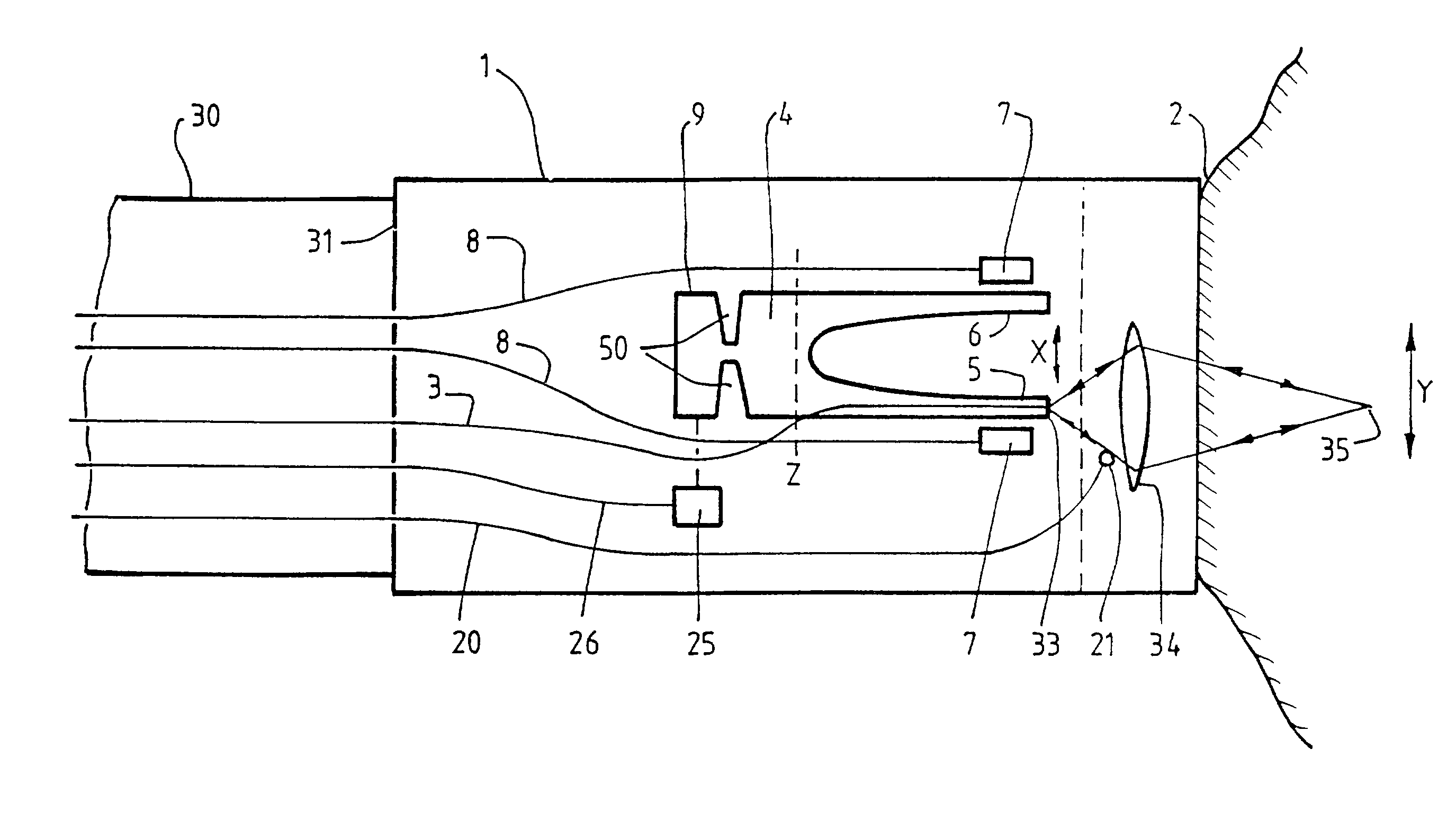
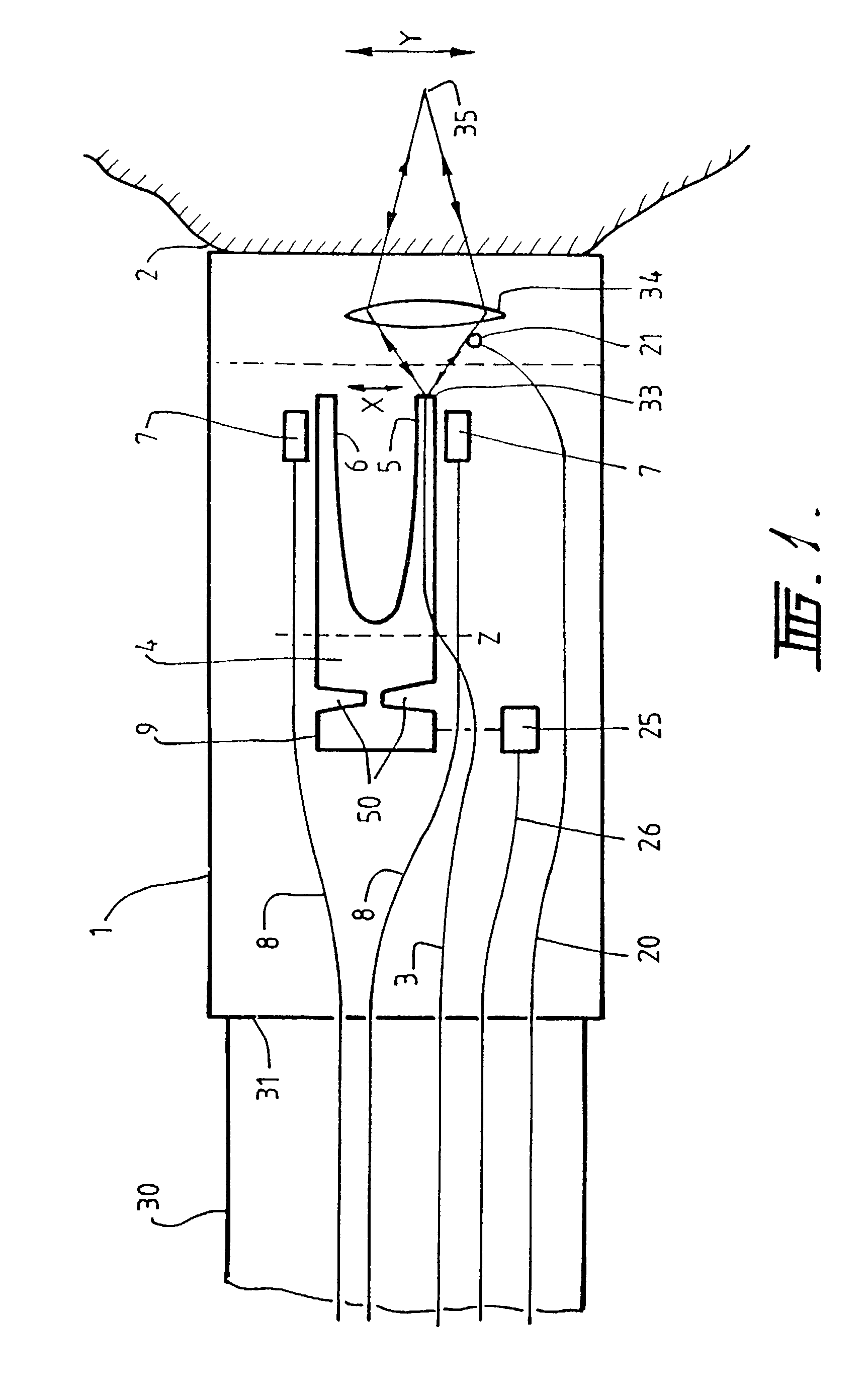
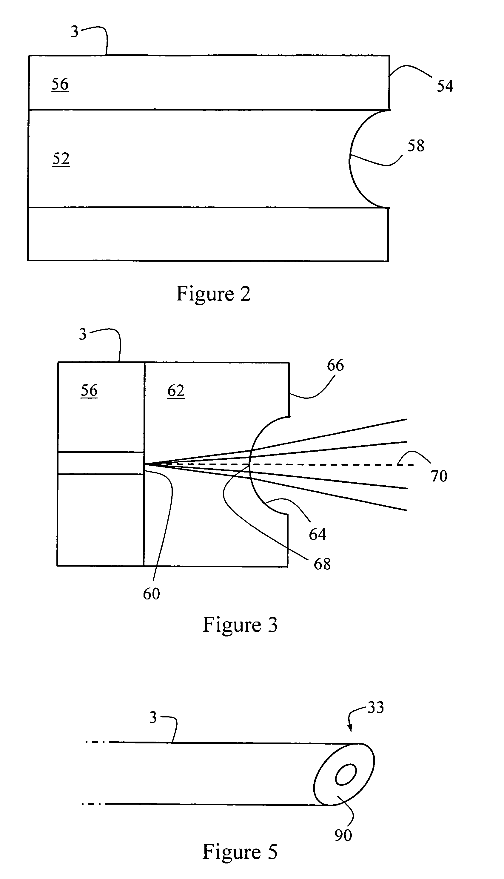
[0041]Referring now to FIG. 1 there is shown an optical head case 1 providing an endoscope head shown in juxtaposition to tissue 2 for in vivo observation. Optical transmission means 3 in the form of a single mode optical fiber passes down flexible endoscope tube 30 from a remotely located laser light source, detector and electronics. The remotely located component may be constructed in accordance with the single fiber embodiments described in U.S. Pat. No. 5,120,953 by Harris and need not be repeated here.

[0042]The single mode optical fiber passes through a rear wall 31 of the optical head case 1 and an exit end 33 of the optical transmission means 3 is attached to a first tine 5 of a tuning fork 4. The tuning fork 4 has slots 50 in each side to reduce transfer of higher mode vibrations from the tines to the mounting portion 9. The tuning fork 4 is driven by electromagnets 7 so that the first tine 5 and second tine 6 have mutually opposite vibration at a frequency of approximately ...


PUM


Abstract

The invention provides a scanning microscope comprising: optical fiber for transmitting a light beam to an exit end of the optical fiber proximate light focusing optics, the light focusing optics focusing the light emerging from the exit end to illuminate a point observation field on or within an object to be examined; and a scanner mounted in an optical head casing with the light focusing optics, to cause the illuminated point observation filed to scan over a two-dimensional cross-section of the object such that an image of the object emanated light over the cross-section is constructible. The scanner comprises a forwardly extending vibratable member and a counterbalance coupled thereto, the point observational field is forward the vibratable member, the vibratable member is coupled to the exit end of the optical fiber to provide the fast scan, the counterbalances reactive forces associated with vibration of the vibratable member and the exit end of the optical fiber during operation, and the light focusing optics is mounted in the optical head casing separately from the vibratable member whereby the light emanating from the exit end of the optical fiber is, during operation, scanned across the light focusing optics.

Description

CROSS REFERENCE OF RELATED APPLICATIONS[0001]This application is a Continuation-In-Part of U.S. application Ser. No. 09 / 462,807 filed on Mar. 27, 2000, now abandoned.BACKGROUND OF THE INVENTION[0002]1. Field of the Invention[0003]This invention relates to scanning microscopes requiring miniature optical heads, in particular but not limited to laser scanning microscopes with miniature heads which can be utilized as an endoscope.[0004]2. Description of the Related Art[0005]In order to construct a scanning microscope which has an optical head small enough to be inserted in the body to act as an endoscope, whereby internal organs of the body may be inspected at a microscopic level, the optical head of the scanning microscope must be able to be located physically independently of the bulky light source and photo-multiplier tube, and also must be miniaturized.[0006]U.S. Pat. Nos. 5,120,953 and 5,161,053 (“Harris” and “Dabbs” respectively) describe how a confocal microscope may be construc...

Claims


Application Information

Patent Timeline
IPC IPC(8): G02B21/00
CPCG02B21/002
Inventor HARRIS, MARTIN RUSSELL
Owner OPTISCAN
Why Eureka
Try Eureka