
In-building code division multiple access wireless system and method

a wireless system and code division technology, applied in the field of code division multiple access communication systems, can solve the problems of voice degradation, inflexibility, high cost of inter-networking communications, etc., and achieve the effects of reducing the time it takes to implement, reducing potential data loss, and less costly

Inactive Publication Date: 2005-11-22
CISCO TECH INC
View PDF8 Cites 17 Cited by
  • Summary
  • Abstract
  • Description
  • Claims
  • Application Information

AI Technical Summary

Benefits of technology

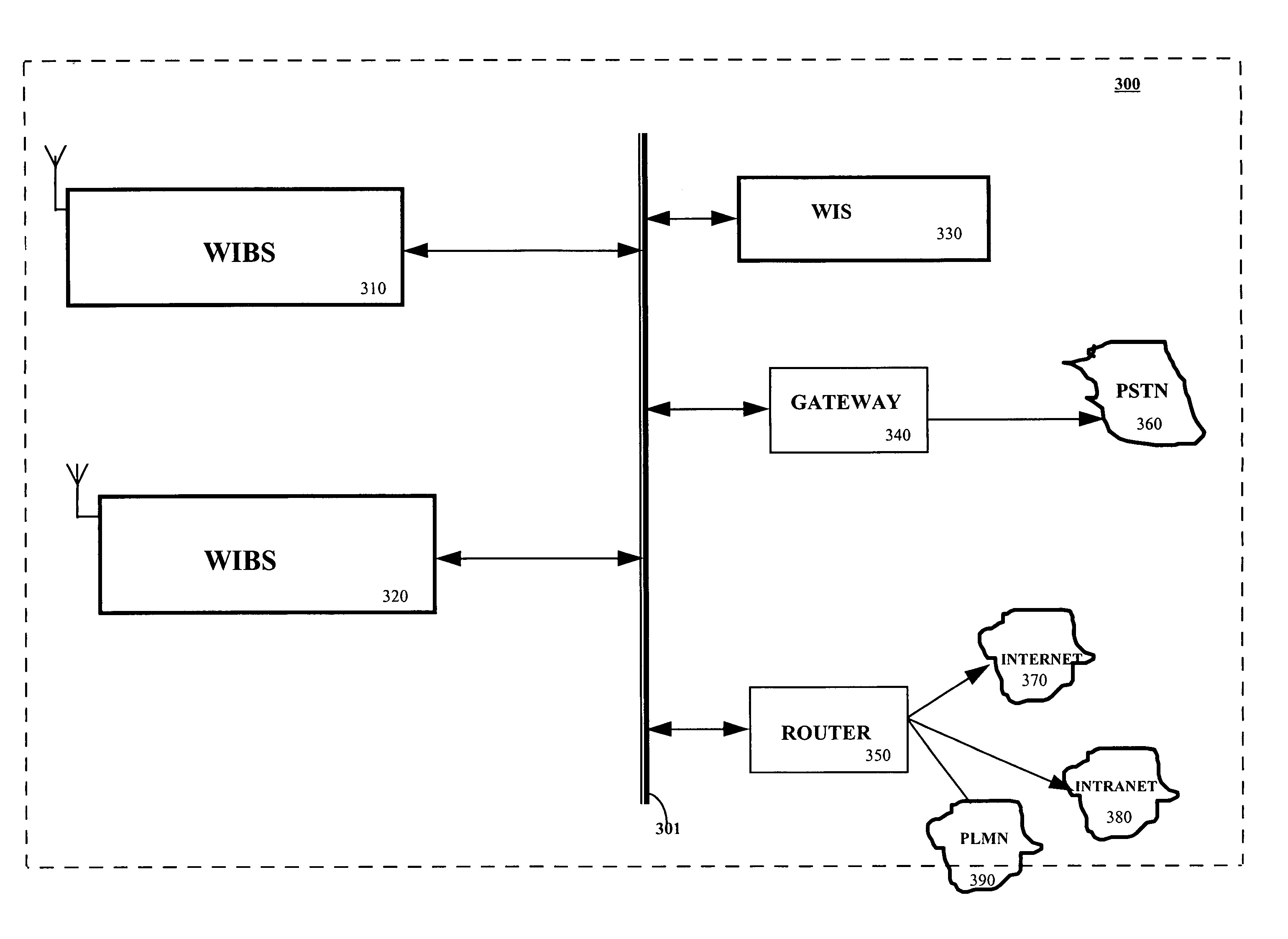
[0027]The present invention is directed to a system and a method for providing an enterprise in-building or campus-wide IP based code division multiple access (CDMA) wireless system. The present invention is capable of handling both voice and data transmission within the CDMA system without the inherent delays and signal quality degradation encountered by conventional CDMA systems. The present invention further provides a system which does not require a dedicated end-to-end communication link when a communicating communication unit initiates or receives a call. This therefore provides a less costly and more efficient way of transmitting data over a CDMA wireless at burst rates higher than conventional CDMA systems.
[0028]The invention includes an integrated wireless internet base station (WIBS) which is connected to the internet and an existing networking infrastructure within an office building or campus. The wireless base station utilizes known ethernet transmission protocols to transmit data over an ethernet back-bone to various wireless communication devices within a building. The wireless base station further includes a call processing module which is capable of determining whether a call originating from or received by the base station to and from a communication unit is either a voice or a data call. The WIBS also integrates the base station control functions of the prior art to reduce call setups between a communication unit and the WIBS, and call handoffs between multiple WIBSs.
[0029]The invention further includes an integrated wireless internet server (WIS) which includes a base station controller module and a mobile switching module. The wireless server manages all calls processed by the base station. In the present invention, because the base station controller functions and the base station functions are integrated in the WIBS and connected to the ethernet back-bone, the base station does not have to send its signals over a long communication link to connect to a communicating communication unit. The integration of the base station controller and the base station further reduces call set-up time between a communicating communication unit and a mobile switching controller.
[0032]The present invention further includes connection logic which allows multiple WIBSs in the system to communicate with each other during a soft handoff of communications between a mobile unit and a WIBS. By enabling adjacent WIBSs to communicate during a soft handoff, the present invention reduces the time it takes to implement soft handoffs in a CDMA system and further reduces potential data loss due to such handoffs.
[0033]The present invention further provides an implementation advantage over the prior art by allowing inter-network communication between the wireless office communication system of the present invention and other mobile networks on the PLMN. The inter-networking communication of the present invention is implemented over an ANSI-41D using the ethernet transport protocol of UDP IIP or TCP IIP transport protocol via an ethernet interface to the ethernet back-bone of the system. The use of the ethernet interface is less costly than the prior art and further allows easy and flexible connectivity to existing in-office, building, or campus networks.

Problems solved by technology

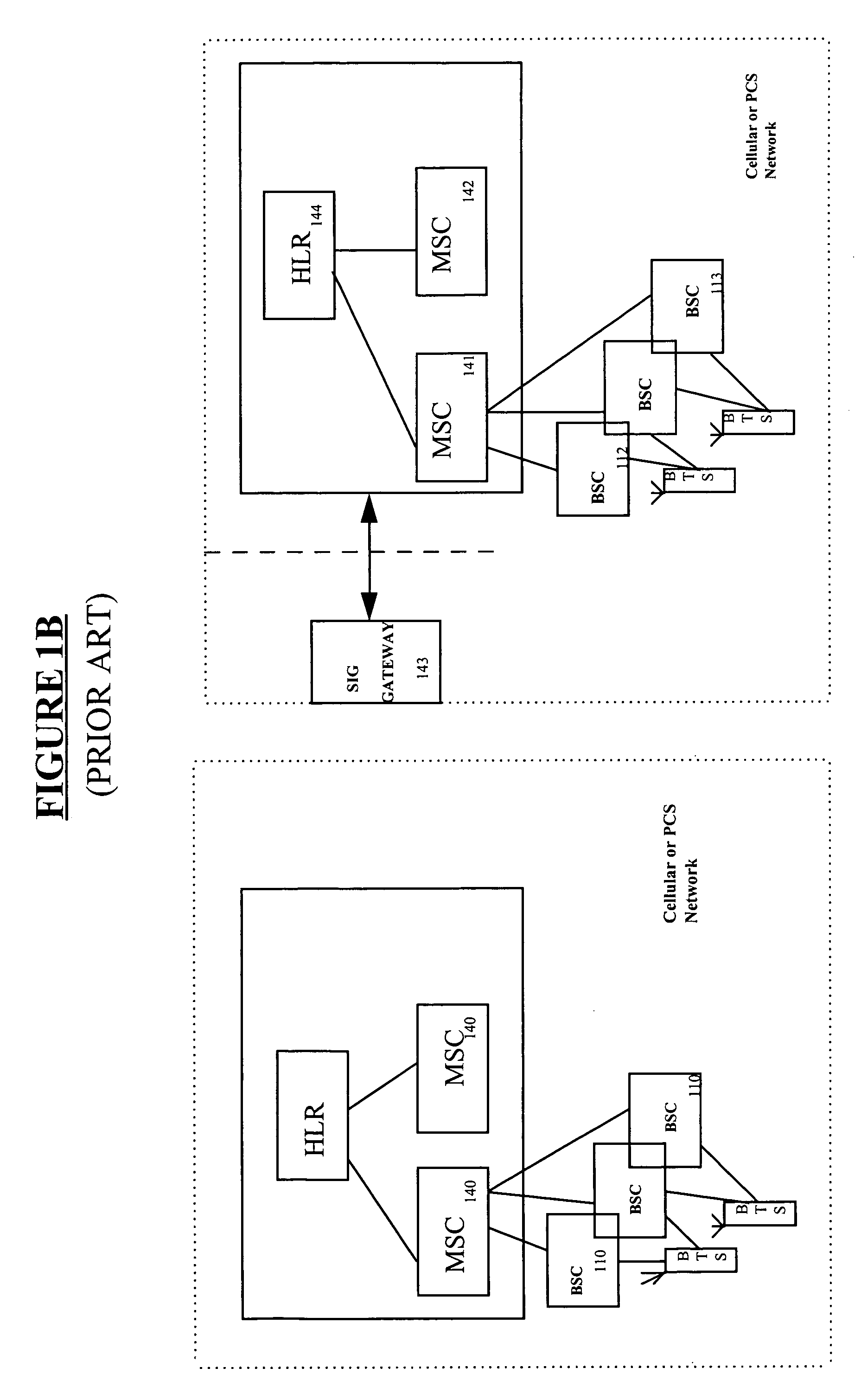
These inter-networking communications are very costly and inflexible.
The SS7 interface card also has some configuration inflexibility due to the proprietary nature of the interface cards.
Although, voice degradation can sometimes be acceptable to a user using the communicating communication unit because the user can always repeat an earlier transmitted message, data communication is more susceptible to degradation.
This is because, in the case of data degradation, the sender of the data does not know at what point that data being sent by a communicating communication unit begins to degrade or is lost.
Consequently, if data transmission begins to degrade or is lost, the communication unit will have to resend the entire data.
Such retransmission can be costly.
Such dedicated end-to-end connection can also be very expensive and time consuming.
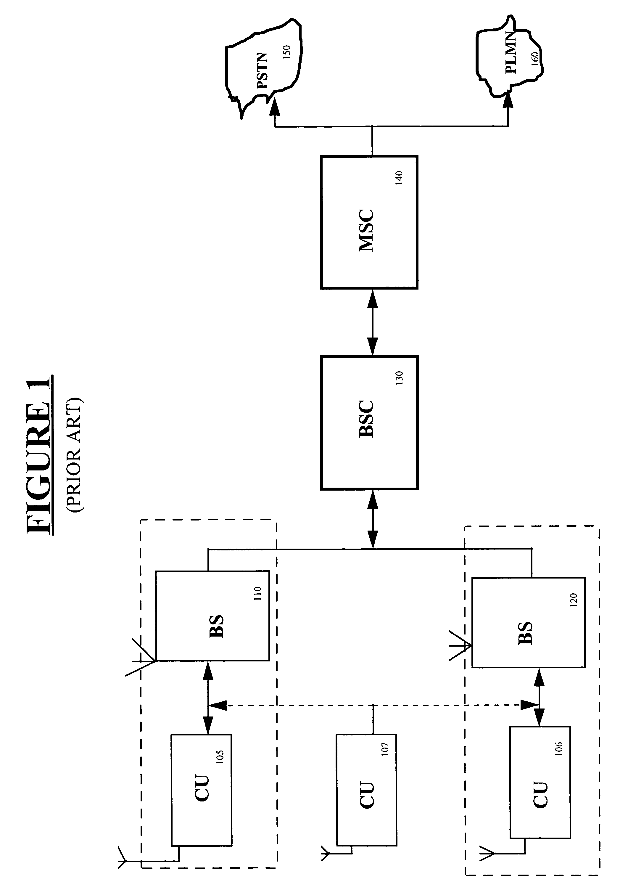
Another problem with the conventional system described in FIG. 1 is that the communication interface between the base station and the base station controller requires proprietary interface technology which makes scaling the system to other communication platforms very cumbersome and expensive.
Furthermore, most of these conventional CDMA communication systems utilize a T1 or E1 communication pathway which have bandwidths of 1.544 Mbps for T1 connections and 2.04 Mbps for E1 connections, and are not known to handle data bursts and therefore are very slow for the transmission of data.
Although such multicarrier systems may alleviate the problems with voice quality degradation, they do not handle data transmission very well.
Thus, these prior art solutions do still have problems with the quality of data calls transmitted with a coverage area from the base stations.
If they are not balanced, system capacity may be reduced as the power control process is disturbed or the hand off region unreasonably expands.
The conventional system described in FIG. 1 or FIG. 2 does not allow each base station to communicate with the other during a handoff since all communication has to go through the base station controller.
This takes time, and in a data traffic transmission it can be costly.

Method used


Image

  • In-building code division multiple access wireless system and method
  • In-building code division multiple access wireless system and method
  • In-building code division multiple access wireless system and method

Examples


Embodiment Construction

[0046]Reference will now be made in detail to the preferred embodiments of the invention, examples of which are illustrated in the accompanying drawings. While the invention will be described in conjunction with the preferred embodiments, it will be understood that they are not intended to limit the invention to these embodiments.

[0047]On the contrary, the invention is intended to cover alternatives, modifications, and equivalents, which may be included within the spirit and scope of the invention as defined by the appended claims. Furthermore, in the following detailed description of the present invention, numerous specific details are set forth in order to provide a thorough understanding of the present invention. However, it will be obvious to one of ordinary skill in the art that the present invention maybe practiced without these specific details. In other instances, well-known methods, procedures, components, and circuits have not been described in detail so as not to unnecess...


PUM


Abstract

A wireless office communication system including a wireless internet base station (WIBS) encompassing a base station controller, a mobile switch controller, and an ethernet interface module for coupling the WIBS to an existing internet protocol (IP) based network. The interface module provides for coupling the WIBS to an ethernet back-bone, a mobile communication unit and a public switch telephone network (PSTN). In one embodiment, the wireless communication system includes a wireless internet server which also encompasses base station controller and mobile switch controller functions to enable the wireless communication system to manage call mobility with the system. In one embodiment, communication between the WIBS and the PSTN is in an IP data protocol format. The WIBs provides control and sequencing of all call control operations by handling both voice and data calls which are transmitted over the ethernet back-bone to the PSN or the internet.

Description

FIELD OF THE INVENTION[0001]The present invention relates generally to the field of wireless communication systems. More particularly, the present invention relates to code division multiple access communication systems.BACKGROUND OF THE INVENTION[0002]Communication systems that utilize coded communication signals are well known in the art. One such system is a code division multiple access (CDMA) cellular communication system such as set forth in the Telecommunications Industry Association / Electronic Industries Association International Standard (TIA / EIA IS-95), hereinafter referred to as 15-95. In accordance with the IS-95, the coded communication signals used in CDMA systems comprise CDMA signals' that are transmitted in a common 1.25 MHz bandwidth to base stations of the system from mobile or wireless communication units, such as cell phones, portable wireless computers, or wireless handheld devices, that are communicating in a specific coverage area of the base station. In conv...

Claims


Application Information

Patent Timeline
Patent Type & Authority Patents(United States)
IPC IPC(8): H04B7/204H04B7/216H04B1/707H04L12/28H04L12/56H04W28/18H04W36/08H04W84/16H04W88/06H04W92/02
CPCH04W84/10H04B2201/70715
Inventor KANG, CHOL SUHYUN, SANG KYOONJOO, KI HYUN
Owner CISCO TECH INC
Learn More