

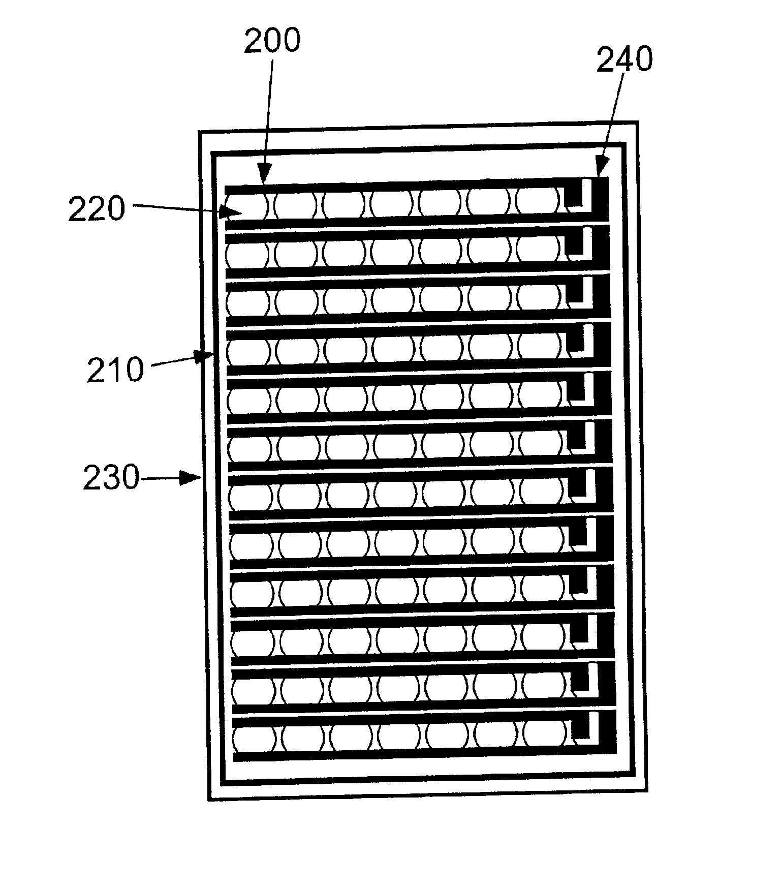
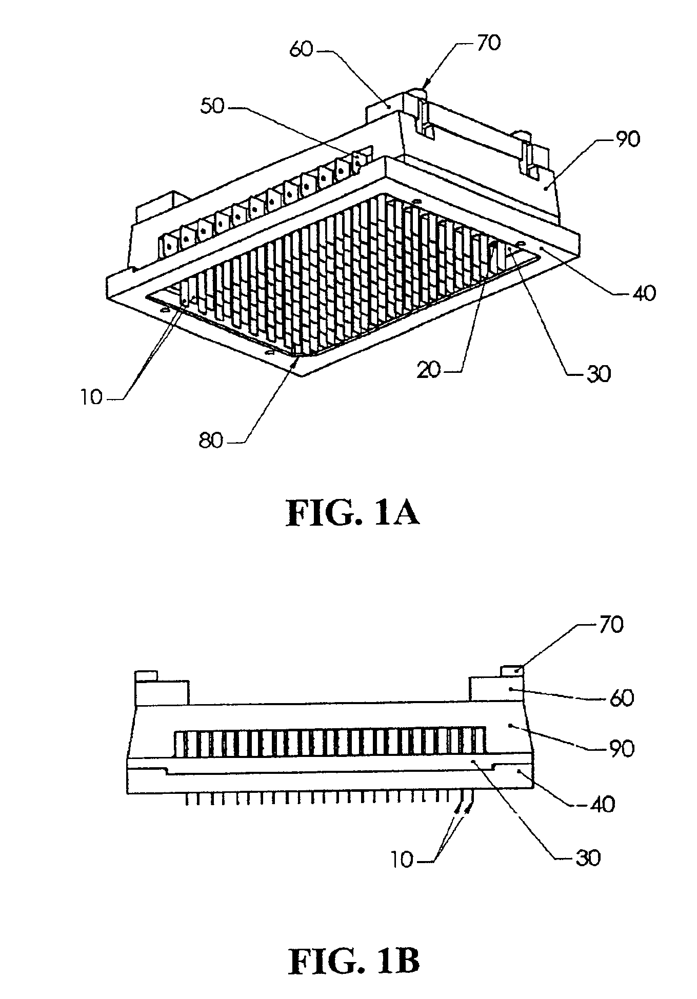
Multi-well plate and electrode assemblies for ion channel assays
a technology of electrode assemblies and multi-well plates, applied in the field of multi-well plates and electrode assemblies for ion channel assays, can solve the problems of low throughput of the patch clamp technique as a general method of pharmacological screening, inability to easily automate the technique, and extensive analysis by skilled electrophysiologists
- Summary
- Abstract
- Description
- Claims
- Application Information
AI Technical Summary
Benefits of technology
Problems solved by technology
Method used
Image

Examples
example 1
1. Example 1
Analysis of the Electrical Field Uniformity of Parallel Plate Electrodes in Standard Round Wells
[0385]To analyze the effect of various electrode, and well designs, a series of two-dimensional numerical simulations of the electric fields were produced using the software analysis package Quickfield™ 4.1, (Student's Version, Tera Analysis, http: / / www.tera-analysis.com). This software package creates coarse-grained mesh type electrical field intensity maps by solving Poisson's equation with a finite-element analysis method in two dimensions. For the purposes of this analysis, the fringing effects due to the gap between the bottom of the electrode and the bottom of the well were ignored, and the voltage drops from the electrodes to the saline were also assumed to be negligible. The spatial resolution of the modeling is approximately 0.5 mm.
[0386]FIG. 7A shows the results of the simulation using 4 mm wide parallel plate electrodes (710) with a 4 mm gap with a standard electric...
example 2
2. Example 2
Analysis of the Electrical Field Uniformity of Pin Electrodes in Standard Round Wells
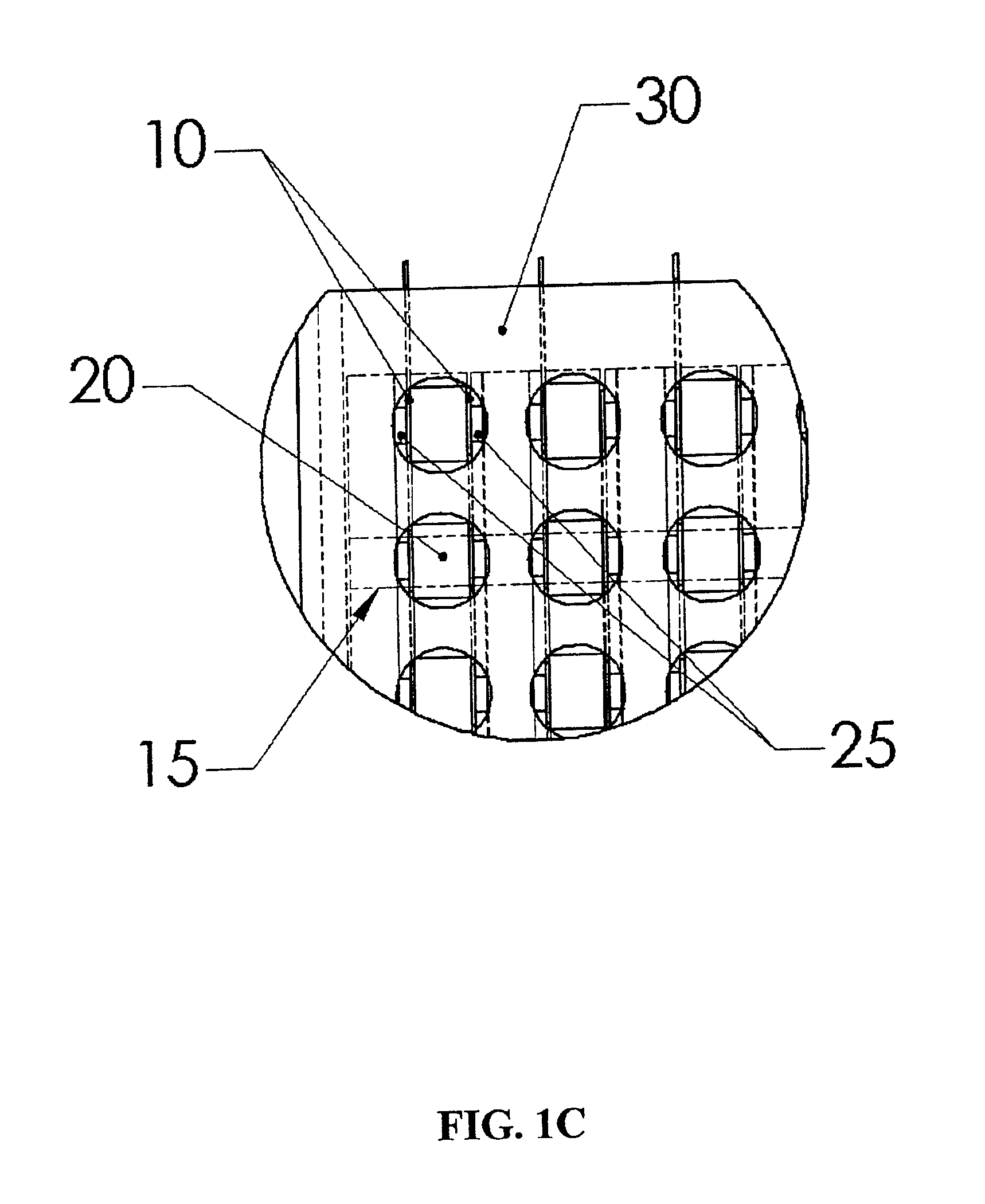
[0387]To determine the predicted field uniformity for two 1.0 mm diameter round pin electrodes placed in a standard 6.2 mm diameter well, separated by a distance of 4.0 mm, simulations were completed with the same conditions and assumptions as described in Example 1.
[0388]In FIG. 7B, the outer solid circle (705) is the edge of the well, the two smaller circles (715) are the electrodes, and the dashed circle in the middle is the area of observation. The gray area (745) is the area in which the electric field remains within ±10% of the mean field in the area of observation. In the white area (735), the field is less than 10% of the mean, and in the black area (755), the field is more than 10% greater than the mean field. Within the area of observation (725), the standard deviation of the field strength is 15% of the mean, and the difference between the maximum and minimum fields is 87% of ...
example 3
3. Example 3
Analysis of the Electrical Field Uniformity of Parallel Plate Electrodes in Square Wells
[0389]FIG. 8A shows a simulation of the field profile for two 6 mm wide parallel plate electrodes with a 4 mm gap in a 6.2 mm square well. In this figure, the outer square (800) is the edge of the well. The two vertical lines (810) are the electrodes. The dashed circle in the middle (820) is the area of observation. Of particular note is that the electric field scale for FIG. 8 has been greatly amplified compared to FIG. 7 to provide contrast for the variations in electrical field intensity. The gray area (840) is the area in which the electric field remains within ±1% of the mean field in the area of observation. In the white area (830), the field is less than 1% of the mean. In this simulation, at no point is the field more than 1% greater than the mean field. Within the area of observation, the standard deviation of the field strength is 0.02% of the mean, and the difference betwee...
PUM
| Property | Measurement | Unit |
|---|---|---|
| distance | aaaaa | aaaaa |
| distance | aaaaa | aaaaa |
| diameter | aaaaa | aaaaa |
Abstract
Description
Claims
Application Information