Ship lock electrical energy generation

a technology of electrical energy generation and lock, which is applied in the direction of dry docks, water-power plants, ship-lifting devices, etc., can solve the problems of discharging all of this energy into head losses, and achieve the effect of optimizing hydraulic energy recuperation, reducing the total head loss over a given period of time, and very small head loss total energy

Inactive Publication Date: 2005-11-29
GENERAL ELECTRIC CANADA INC A CO OF CANADA
View PDF20 Cites 14 Cited by
  • Summary
  • Abstract
  • Description
  • Claims
  • Application Information

AI Technical Summary

Benefits of technology

[0006]The present invention relates to the use of a hydraulic turbine and/or pump-turbine to regulate the discharge flow rates in ship locks to an approximate constant value during the majority of the water transfer cycle resulting in a diminishing of total energy of head losses and to enable the recuperation of the unused hydraulic energy for generation as electricity. The difference in water levels on opposite sides of the ship lock constitutes poten

Problems solved by technology

In the traditional operation of locks, all o

Method used


Image

  • Ship lock electrical energy generation
  • Ship lock electrical energy generation
  • Ship lock electrical energy generation

Examples


Embodiment Construction

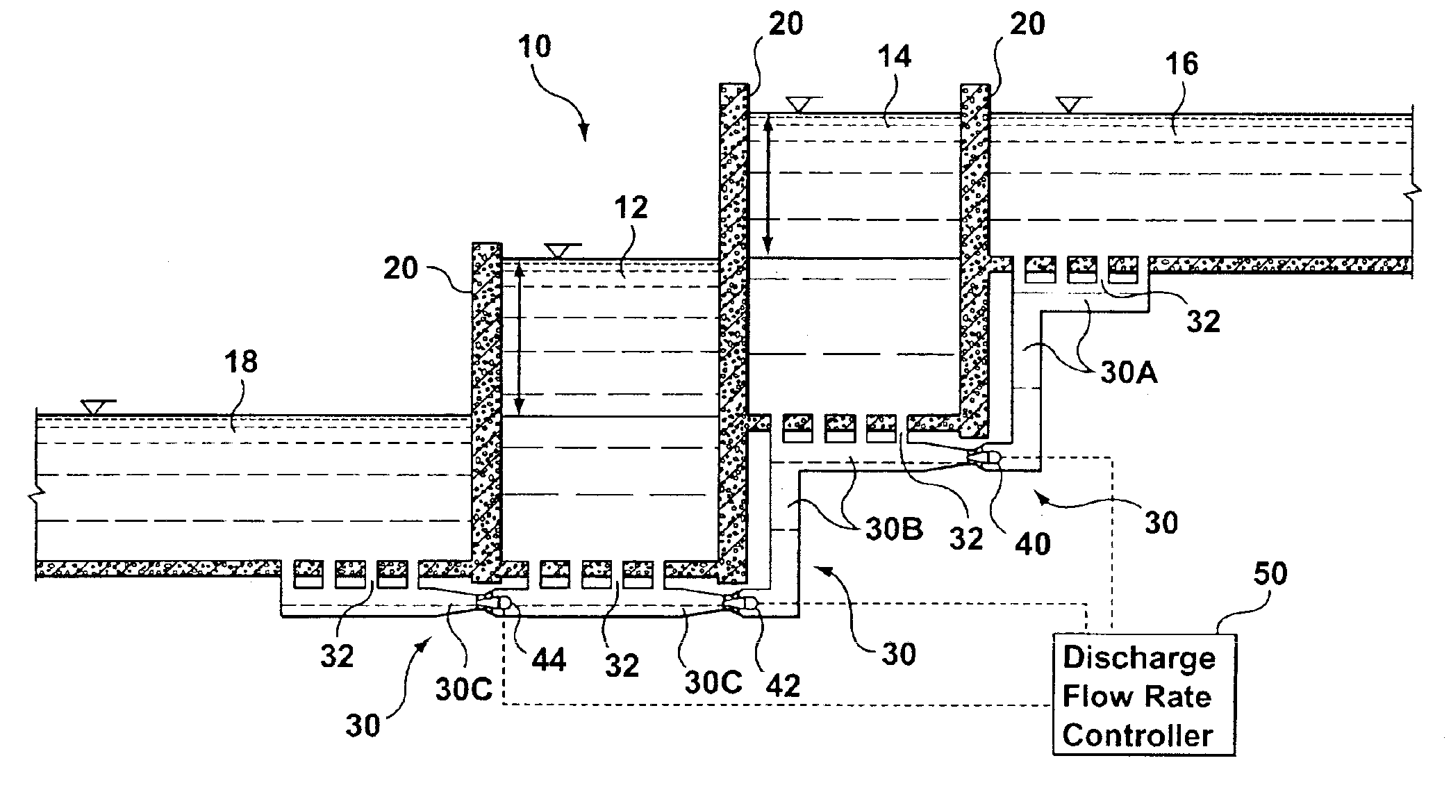
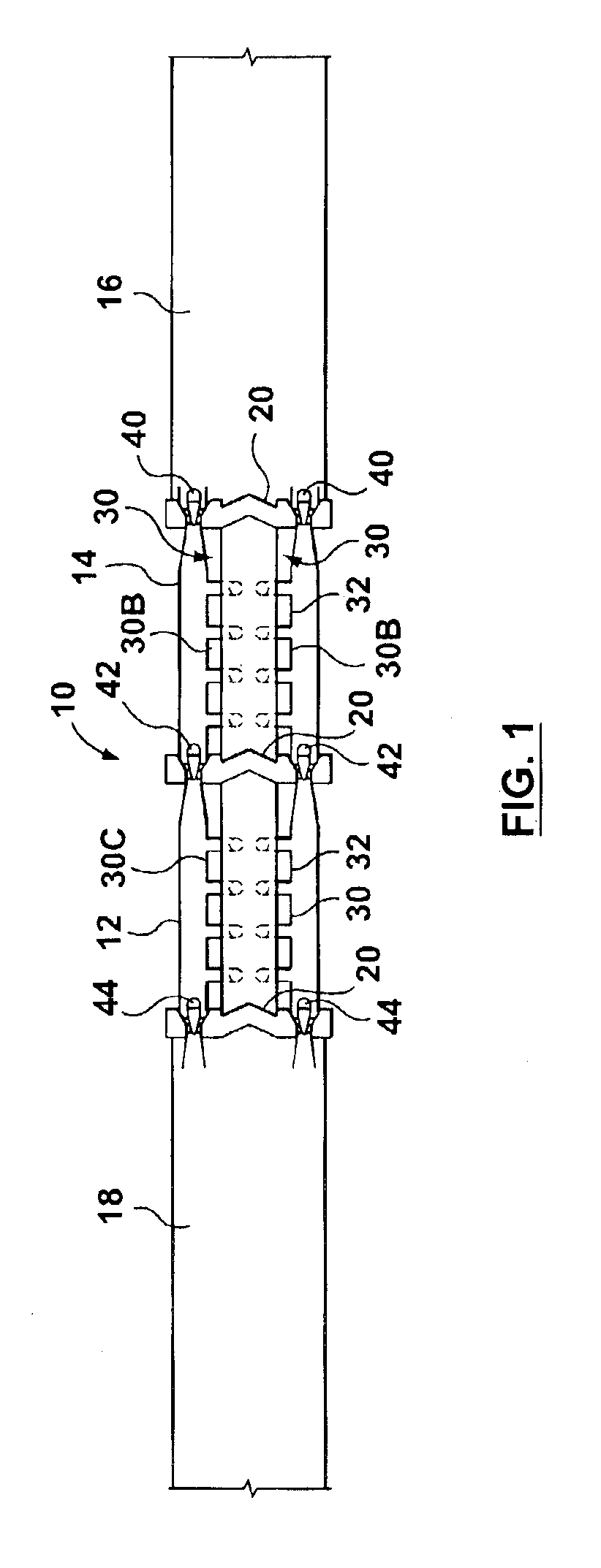
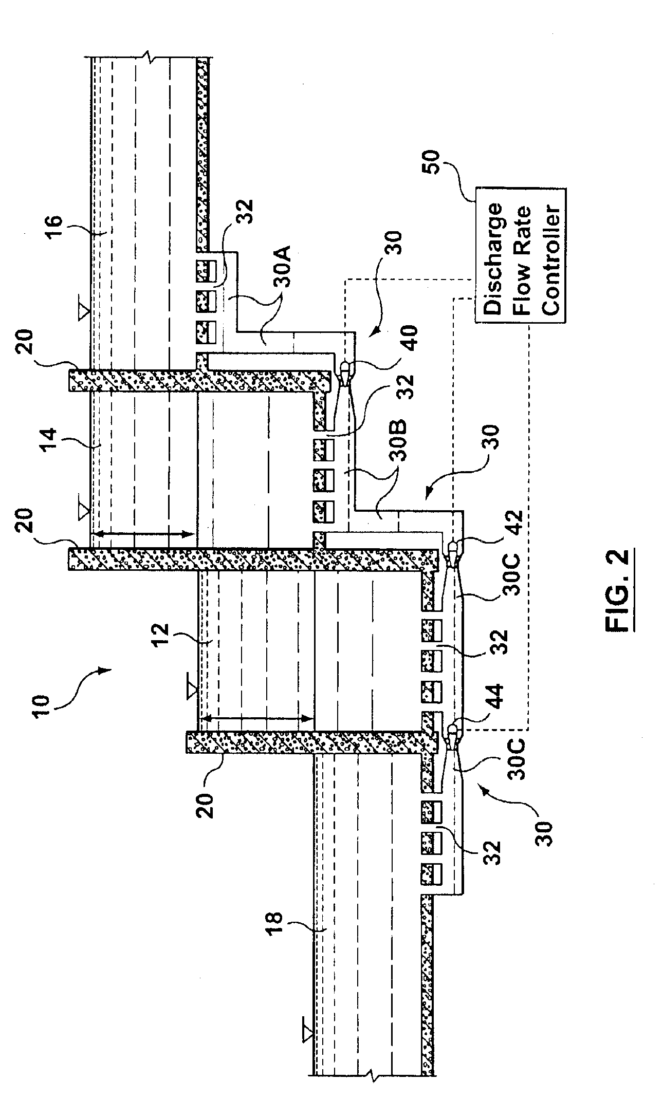
[0021]Referring to FIGS. 1 and 2, there is shown a canal lock system 10 that utilizes two ship locks 12 and 14 respectively located between an upper body of water 16 and a lower body of water 18. It should be understood that the number of ship locks illustrated is two locks and that the number could be only one lock or three or more locks between the bodies of water 16 and 18.

[0022]Each ship lock 12 and 14 has a pair of spaced apart gates 20 for permitting passage of ships to and from the ship locks 12 and 14 when the gates are alternately opened and closed. Ship locks 12 and 14 share a common gate between them.

[0023]Between the bodies of water 16 and 18 extends fluid communicating passageways 30 for coupling the upper body of water 16 with the ship locks 12 and 14, and the lower body of water 18. The fluid communication passageways 30 are underground culverts that communicate with the bodies of water16 and 18 and the ship locks 12 and 14 through controlled access ports 32 on the fl...


PUM


Abstract

A ship lock utilizes a hydraulic turbine and/or pump-turbine to regulate the discharge flow rates through the ship lock to an approximate constant value during the majority of the water transfer cycle resulting in a diminishing of total energy of head losses and to enable the recuperation of the unused hydraulic energy for generation as electricity. The difference in water levels on opposite sides of the ship lock constitutes potential hydraulic energy. By regulating the discharge, the total head losses over a given period of time diminish very significantly, thus giving an opportunity for optimization of hydraulic energy recuperation.

Description

FIELD OF THE INVENTION[0001]The present invention relates to a method and system for generating electrical energy during the changing of the water levels in ship locks.BACKGROUND OF THE INVENTION[0002]A ship lock, often in a canal system, operates to connect two bodies of water at different water levels by alternate lowering and raising of the water level in the ship lock. Ship locks are operated using the gravity force to transfer a volume of water from one side of a lock gate to its other side. Once water levels have equilibrated, the lock gate can be opened for the ship to move through the gate.[0003]U.S. Pat. No. 4,310,769 issued Jan. 12, 1982 teaches a ship lock system having one or more underground hydroelectric pumped-storage units which generate electrical energy. Water from the ship lock is drained to a lower reservoir when the ship lock water level is lowered. The water passes through a penstock and past a pump-turbines to generate electrical energy. The reservoir collects...

Claims


Application Information

Patent Timeline
IPC IPC(8): E02B9/00E02C1/00
CPCE02B9/00E02C1/00Y02E10/22Y02E10/20Y02A10/30
Inventor DESY, NORMANVIRTA, PEKKA
Owner GENERAL ELECTRIC CANADA INC A CO OF CANADA
Why Eureka
Try Eureka