
Microelectronic stimulator array for stimulating nerve tissue

a micro-electronic stimulator and nerve tissue technology, applied in the field of neurosurgical prosthesis, can solve the problems of preventing certain image processing functions, creating an electrical interface between the high-density electrode array and the curved surface of the retina, and direct electrical stimulation of the ganglion cells

Inactive Publication Date: 2005-11-29
THE UNITED STATES OF AMERICA AS REPRESENTED BY THE SECRETARY OF THE NAVY
View PDF1 Cites 34 Cited by
  • Summary
  • Abstract
  • Description
  • Claims
  • Application Information

AI Technical Summary

Benefits of technology

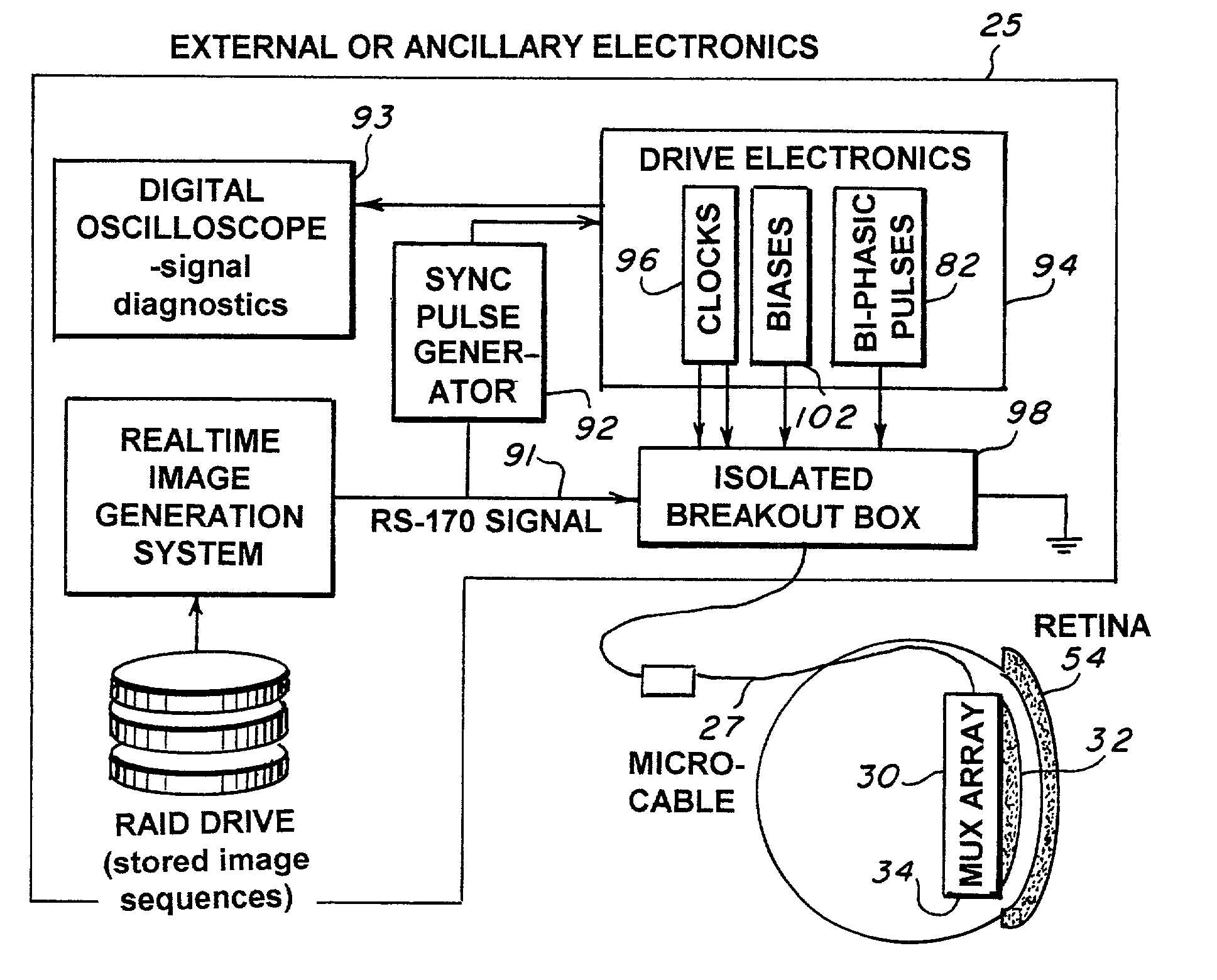
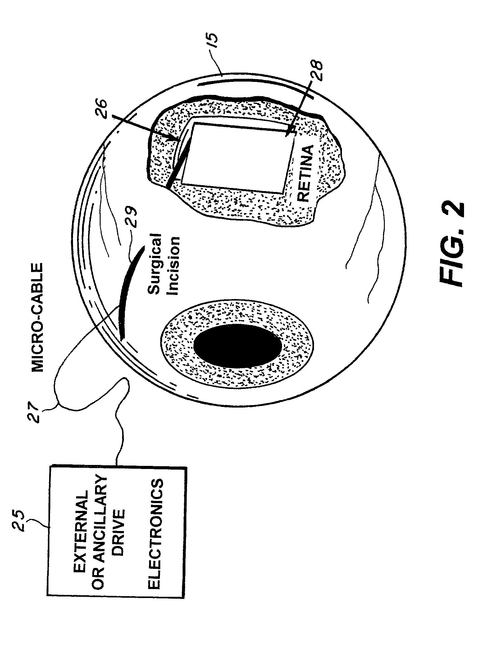
[0014]These and other objects are accomplished by the retinal prosthesis test device and retinal implant device comprising two basic technologies—nanochannel glass (NGC) electrode arrays and infrared focal plane array (IRFPA) multiplexers. In the retinal prosthesis test device, the device is positioned against the retina using standard retinal surgical techniques in an operating room environment. The device is comprised of a thin wafer of glass (NGC) with very small channels perpendicular to the plane of the wafer. The channels are filled with a good electrical conductor forming microwires with one surface of the glass being ground to a spherical shape consistent with the radius of curvature of the inside of the retina. Electrical conductors protrude slightly from the NGC on the curved surface to form electrodes. The NGC is hybridized to a silicon IRFPA multiplexer using indium bump bonds. An image is serially input into the multiplexer via a very narrow, flexible micro-cable. The multiplexer is mounted on a ceramic carrier such that interconnecting bond pads on each are in close proximity to one another. A video image is read into each of the unit cells on the multiplexer in pixel-by-pixel manner. Discrete samples of the analog video are input and stored as electrical charge...

Problems solved by technology

There are a number of technical issues to be addressed in designing and fabricating a retinal prosthesis device, particularly if the device is to generate a high resolution image.
First, there is the issue of creating an electrical interface between the high-density electrode array and the curved surface of the retina.
Third, direct electrical stimulation of the ganglion cells precludes certain image processing functions that normally would have occurred in earlier layers of the retina.

Method used


Image

  • Microelectronic stimulator array for stimulating nerve tissue
  • Microelectronic stimulator array for stimulating nerve tissue
  • Microelectronic stimulator array for stimulating nerve tissue

Examples


Embodiment Construction

[0029]In the preferred embodiment of a retinal prosthesis test device utilizing a microelectronic stimulator array 30, as shown in FIG. 3a, the nanochannel glass (NGC) electrode arrays 32 is hybridized to silicon multiplexer 34 using indium bump bonds, a technique from infrared (IR) focal plane array (IRFPA) multiplexers. An image is serially input onto the multiplexer 34 via a very narrow, flexible micro-cable 36. The micro-cable 36 is approximately six inches in length and is custom made using gold leads patterned on polyimide strips. A ceramic carrier 38 with gold-filled via holes 42 provides a mechanically convenient means of routing interconnects from the top-side 44 of the ceramic carrier to the back-side 46. By designing the ceramic carrier such that the top-side contacts to the via-holes 44 are in close proximity to bond pads 48 on the silicon multiplexer 34, the interconnection may be made with conventional tab-bonds 52 (thin gold ribbons fused to interconnects with mechani...


PUM


Abstract

The retinal prosthesis test device is comprised of a thin wafer of glass made from nanochannel glass (NGC) with very small channels perpendicular to the plane of the wafer filled with an electrical conductor forming microwires. One surface of the glass is ground to a spherical shape consistent with the radius of curvature of the inside of the retina. The NGC is hybridized to a silicon de-multiplexer and a video image is serially input to a narrow, flexible micro-cable and read into a 2-D array of unit cells in a pixel-by-pixel manner which samples the analog video input and stores the value as a charge on a MOS capacitor. After all unit cells have been loaded with the pixel values for the current frame, a biphasic pulse is sent to each unit cell which modulates the pulse in proportion to the pixel value stored therein. Because the biphasic pulses flow in parallel to each unit cell from a global external connection, the adjacent retinal neurons are all stimulated simultaneously, analogous to image photons stimulating photoreceptors in a normal retina. A permanent retinal implant device uses a NGC array hybridized to a silicon chip, the image is simultaneously generated within each cell through a photon-to-electron conversion using a silicon photodiode. The photons propagate directly through into the backside of the device. Electrical power and any control signals are transmitted through an inductively driven coil or antenna on the chip. The device collects the charge in storage capacitors via the photon-to-electron conversion process, stimulates the neural tissue with biphasic pulses in proportion to the stored charges, and resets the storage capacitors to repeat the process.

Description

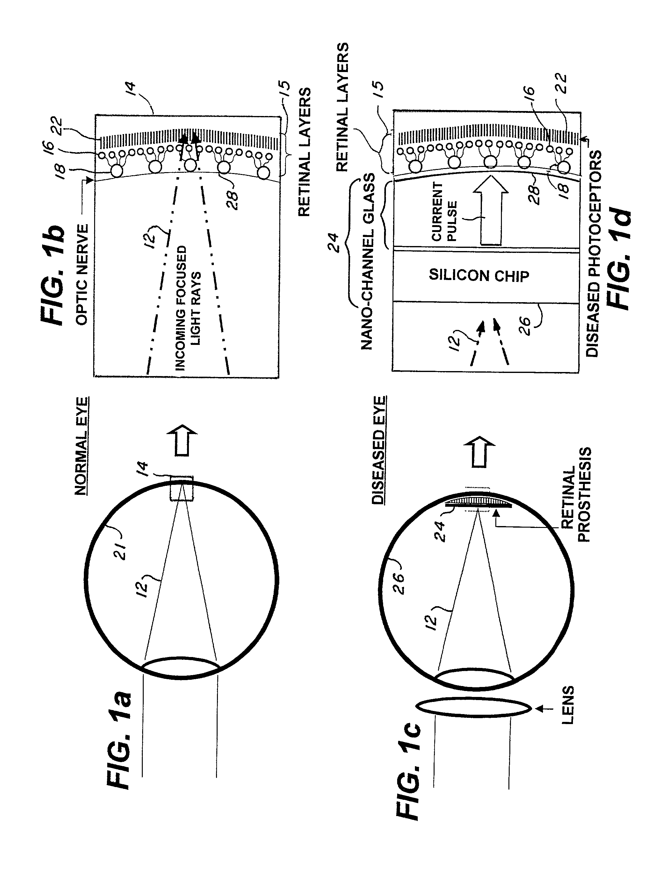
[0001]This is a division of Application No. 09 / 635,226, filed Aug. 9, 2000, now U.S. Pat. No. 6,393,327.BACKGROUND OF THE INVENTION[0002]1. Field of the Invention[0003]This invention deals generally with neural prosthesis, specifically the concept of achieving a retinal prosthesis for blind patients through the creation of an electrical interface between a high-density electrode array and the curved surface of the retina.[0004]2. Description of the Related Prior Art[0005]There is a great deal of recent interest in the area of neural prosthesis, specifically the concept of achieving a retinal prosthesis for blind patients has been hypothesized by a number of researchers and is an active area of medical research. In a normal eye, in a basic concept 10, FIGS. 1a and 1b shows a ray trace of two photons 12 focused on a retina 21. Note that the incoming photons 12 pass through several layers of transparent retinal cells 16 and 18 before being absorbed by the photoreceptors 22. In a damage...

Claims


Application Information

Patent Timeline
IPC IPC(8): A61F2/14A61N1/05A61N1/36
CPCA61N1/0543A61N1/36046
Inventor SCRIBNER, DEAN
Owner THE UNITED STATES OF AMERICA AS REPRESENTED BY THE SECRETARY OF THE NAVY
Learn More