
Flow probe pipe size detector

Inactive Publication Date: 2005-12-13
ONICON INC
View PDF9 Cites 39 Cited by
  • Summary
  • Abstract
  • Description
  • Claims
  • Application Information

AI Technical Summary

Benefits of technology

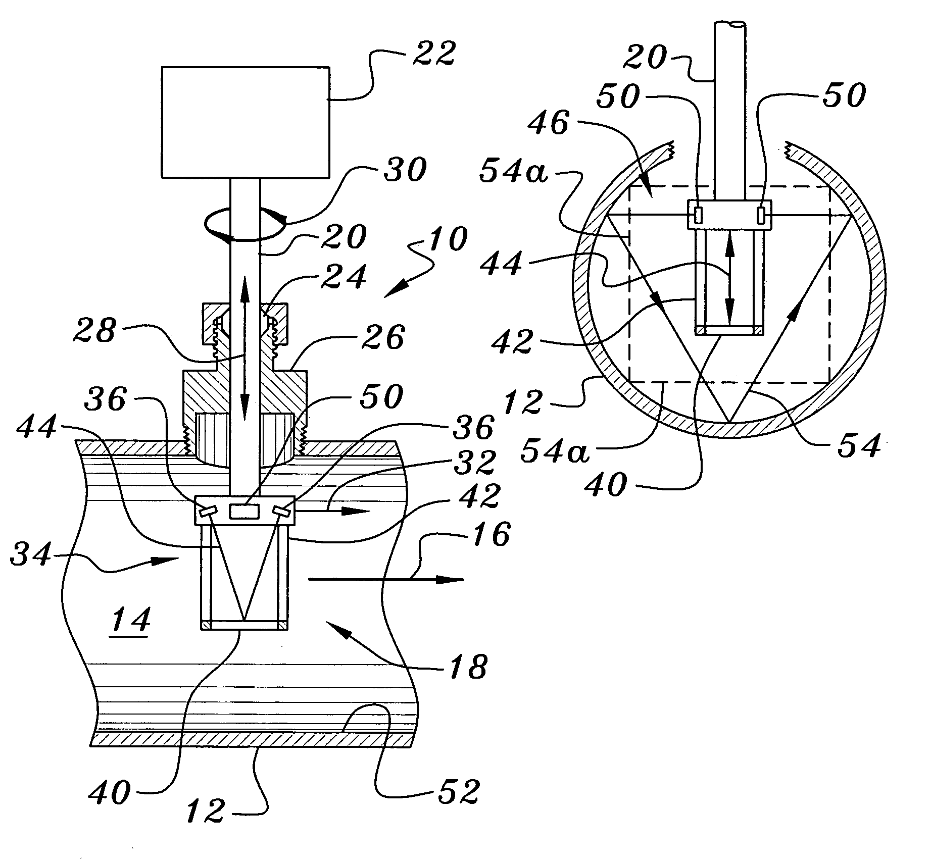
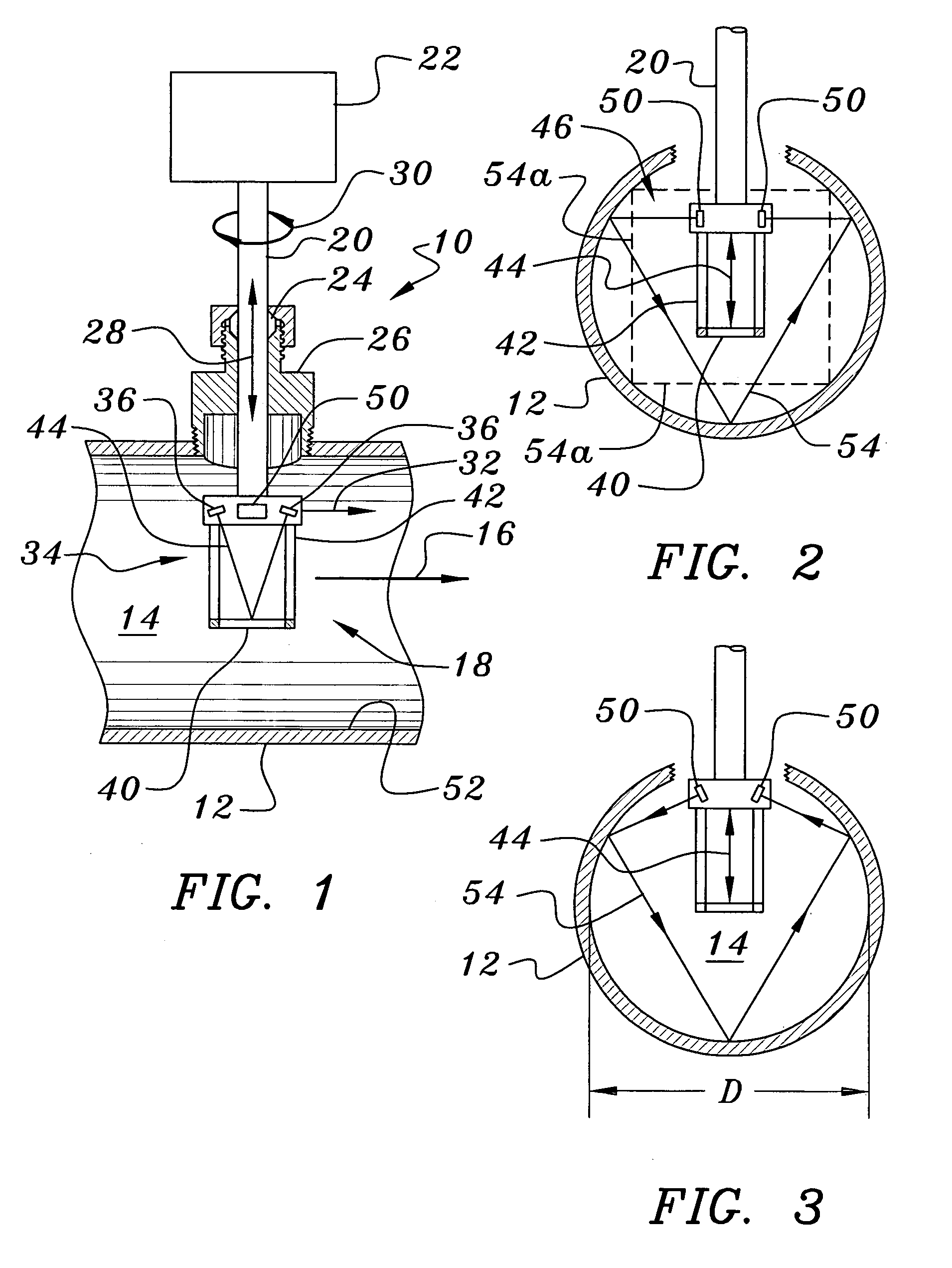
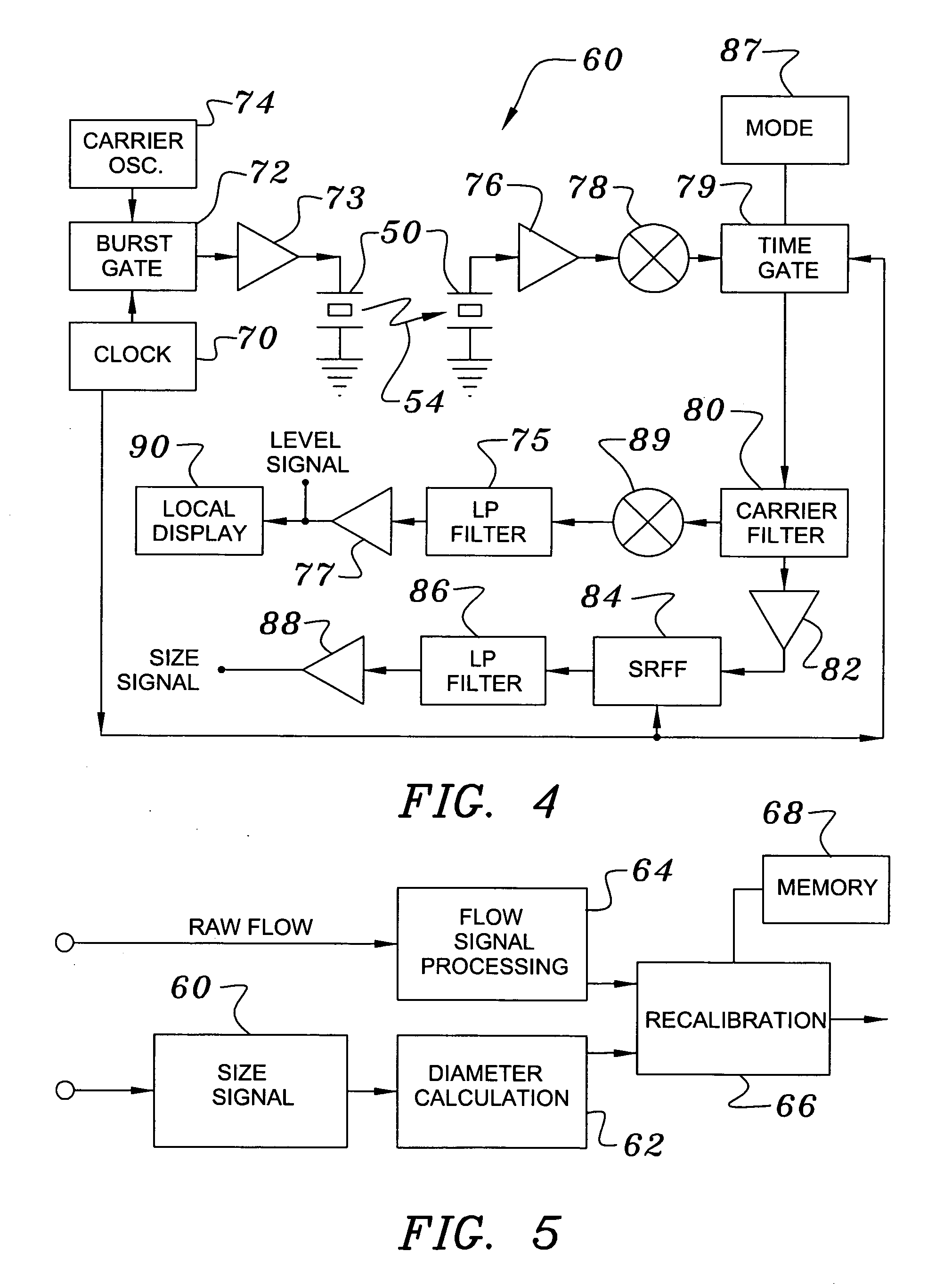
[0009]In one embodiment of the present invention, a probe-type flow sensor is improved by adding an acoustic time-of-flight size measuring device to the sensing head. In a preferred arrangement of this sort a transmitting transducer directs an acoustic beam so as to make a plurality of reflective contacts with the pipe's interior wall prior to reaching a receiving transducer. This arrangement provides for an accurate measurement of the internal diameter (ID) of the pipe and also enables the magnitude of the received acoustic signal to be used as an indicator of both insertion depth and angular orientation with respect to the pipe axis. In addition, the arrangement provides a means for sensing acoustic path attenuation caused by factors such as the buildup of deposits. This method differs from that taught by Feldman et al. in U.S. Pat. No. 6,584,860 in that the pipe ID is actually measured, rather than taking Feldman et al.'s approach of assuming that a nominal pipe ID is equal to the actual one.
[0010]In one preferred embodiment of the present invention the acoustic distance measuring device is attached to the flow sensing probe so that when the flow sensing head is oriented with its axis of measurement aligned with the axis of the pipe, the acoustic measuring device is positioned to transmit and receive its acoustic signals perpendicular to the pipe axis. In a fluid-filled pipe these acoustic waves are multiply reflected by the pipe wall and propagated along chordal paths through the cross section of the pipe. Because the acoustic transit time is proportional to the ID of the pipe, this allows for measurement of the pipe ID, which is then used to adjust the calibration of the flow rate measurement by replacing a nominal pipe ID value with the measured one. This, of course, may be either a manual adjustment or an automatic trimming of the flow sensor's span calibration. Moreover, the magnitude of the signal detected by the receiving transducer of the acoustic distance measuring device is an indication of the optimization of the acoustic path and of possible presence of scale or other internal deposits. When this preferred probe is adjusted to the optimum depth and orientation angle, the signal has a maximum level. By adjusting the probe mounting during its installation for this maximum level, an installation is made which more closely approximates the factory calibration conditions than that which would result if the installer merely used relatively crude mechanical measurements and his visual aiming abilities to set insertion depth and orientation. To facilitate this calibration, the flow sensing probe may contain a display device such as an analog or digital voltmeter or array of LEDs to indicate the received signal level.

Problems solved by technology

Because these probes are generally used to measure flow rate by sampling a small portion of the flow profile and deriving from that measurement the volumetric flow rate based upon an assumed internal pipe diameter, a pipe diameter different from that assumed can introduce significant error into the derived results.
The potential error related to this variation in internal diameter has not received much attention in the past because of the acceptance of the probe type of flow sensing instrument as one of relatively low accuracy and because of the difficulty in measuring the internal diameter of installed pipes.
This is a recognized problem that is not solved by the prior art of using a single, pre-set diameter through the service life of a given flow sensor.

Method used


Image

  • Flow probe pipe size detector
  • Flow probe pipe size detector
  • Flow probe pipe size detector

Examples


Embodiment Construction

[0020]In studying this Detailed Description, the reader may be aided by noting definitions of certain words and phrases used throughout this patent document. Wherever those definitions are provided, those of ordinary skill in the art should understand that in many, if not most instances, such definitions apply to both preceding and following uses of such defined words and phrases. At the outset of this Description, one may note that the terms “include” and “comprise,” as well as derivatives thereof, mean inclusion without limitation; and the term “or,” is inclusive, meaning and / or.

[0021]The term “insertion probe” as used herein, denotes an elongated member designed to be inserted into a pipe or other vessel so that a sensing element on, or closely adjacent, the inserted end of the probe is at a selected insertion depth. More specifically, a “flow probe”, as used herein, provides the conventional denotation of a portion of a flow sensor configured to be inserted into a pipe. A “flow ...


PUM


Abstract

An acoustic time-of-flight size measuring device is added to the sensing head of an insertion probe sensor which may be used for measuring the flow of fluid in a pipe. The size-measuring device defines an acoustic beam making a plurality of reflective contacts with the pipe's interior wall. A time-of-flight measurement of this path length provides an accurate measurement of the internal diameter of the pipe. The magnitude of the transit time signal can also be used as an indicator of both insertion depth and angular orientation of the probe with respect to the pipe axis. In addition, the arrangement allows one to sense acoustic path attenuation caused by factors such as the buildup of deposits.

Description

BACKGROUND OF THE INVENTION[0001]1. Field of the Invention[0002]The present invention relates to apparatus and methods of compensating for the variation of internal diameters of pipes in which sensing probes are inserted, optimizing their insertion depth and orientation during installation, and detecting the accumulation of pipe wall deposits.[0003]2. Background Information[0004]Insertion probes for detecting the flow of fluids are typically mounted in round pipes having internal diameters that are not precisely known. Because these probes are generally used to measure flow rate by sampling a small portion of the flow profile and deriving from that measurement the volumetric flow rate based upon an assumed internal pipe diameter, a pipe diameter different from that assumed can introduce significant error into the derived results.[0005]The magnitude of the problem can be seen by considering the ASTM A 106 dimensional limits for a range of diameters about a nominal diameter of six inc...

Claims


Application Information

Patent Timeline
IPC IPC(8): G01F1/66G01F15/00G01F15/18
CPCG01F1/66G01F1/662G01F1/667G01F5/00G01F15/00G01F15/18G01N2291/02836G01F1/002G01B17/00
Inventor FELLER, MURRAY F.
Owner ONICON INC
Learn More