Method and device for controlling ignition timing of ignition device for internal combustion engine

a technology of capacitive discharge and ignition device, which is applied in the direction of engine starters, automatic control of ignition, machines/engines, etc., can solve the problems of complicated handling, difficult re-starting of internal combustion engines, and complicated handling

Inactive Publication Date: 2005-12-13
IIDA ELECTRIC IND
View PDF29 Cites 14 Cited by
  • Summary
  • Abstract
  • Description
  • Claims
  • Application Information

AI Technical Summary

Benefits of technology

[0032]The invention as set forth in claim 1 is adapted to obtain the cycle detection signal, the peak voltage detection signal, and the start-up voltage detection signal from the output voltage from the generator coil in the ignition device for the capacitive discharge internal combustion engine. The ignition signal is output in accordance with an ignition timing signal provided by the cycle detection signal, the peak voltage detection signal, or the start-up voltage detection signal, thus eliminating the need for a pulser coil or a coil for outputting the ignition signal or detecting an RPM.
[0096]Furthermore, the quick recharging portion basically includes the rechargeable switching element for being self-triggered in accordance with the reverse voltage portion of the output voltage, and the turn-off transistor for placing the rechargeable switching element in a non-conducting state in response to the trigger signal from the microcomputer portion, providing a very simple configuration to the quick recharging portion.

Problems solved by technology

This stop means employing only the manual stop switch has a disadvantage in that although a stop switch formed of a push-button self-recovery normally open contact switch provides an easy stop operation, it requires continuously pressing the stop switch until the internal combustion engine comes to a complete stop, thus complicating its handling.
On the other hand, such a disadvantage is also provided where the internal combustion engine may be started without having switched the stop switch to an OFF state, thereby making it difficult to re-start the internal combustion engine.
H-7-26602 requires a pulser coil external to the generator coil, thereby raising a problem of the generator being made complicated in structure, and requiring high dimensional accuracy during assembly leading to complicated handling.
There was also another problem in that an ignition operation is performed even at the time of a low speed operation of an engine which cannot provide a voltage available to the operation of the microcomputer, causing the engine to operate very unstably at a low speed and especially to operate unstably at the time of a start-up.
There was still another problem in that the low-speed ignition position signal supplied by the pulser coil is always generated at constant rotational angle intervals because the pulser coil is fixed immovably, thereby making it impossible to provide an advancing operation suitable for the speed of the engine in the low speed region and thus eliminate the instability in low speed operation of the engine.
Thus, there was another problem in that occurrence of variations in rotation typical of the low speed region, causing the RPM of the engine to be reduced at the time when the piston approaches the top dead center, would result in a significant advance in ignition timing, thereby leading to the possibility of a kickback occurrence.
Thus, there was another problem in that it proves difficult to smoothly reduce the RPM of the internal combustion engine.
However, this eliminates the need for the ignition recovery control in the over-rotation prevention control mode, providing no meaning to the aforementioned prior art.
In this case, there is a problem in that the difference between the RPM in the misfire state and the RPM at the time of the ignition state being restored is likely to become bigger, thereby causing a load to be operated under significant variations in speed and lack of smoothness.
However, the ignition control circuit serving as a main portion of the ignition device requires proper setting of a circuit constant such as impedance, complicated handling such as setting of ratings of each of the parts constituting the stop means, and complicated connections to the ignition control circuit.
This raised a problem of requiring time and effort for handling and implementation.
There was also a problem in that occurrence of a failure such as a short-circuited or open rechargeable / dischargeable capacitor or switching element leads to a loss of a stop function thus providing no fail-safe function.
Thus, this raised a problem in that forming the stop means requires a number of parts, thereby making its structure complicated as well as raising its costs.
H-7-26602, the rising edge of a recharge voltage, at the time of start-up of the internal combustion engine, in a constant voltage power supply portion for recharging the reverse voltage portion of the generator coil is delayed due to the current limiting resistor provided for security of the input portion, thereby making it impossible to start up the microcomputer quickly.
Thus, there was another problem in that since a recoil starter had to be used to rotate the internal combustion engine at least three to four times to provide ignition, its start-up characteristics were not always good.

Method used


Image

  • Method and device for controlling ignition timing of ignition device for internal combustion engine
  • Method and device for controlling ignition timing of ignition device for internal combustion engine
  • Method and device for controlling ignition timing of ignition device for internal combustion engine

Examples


Embodiment Construction

[0123]Now, the present invention will be explained below with reference to the accompanying drawings in accordance with the embodiments.

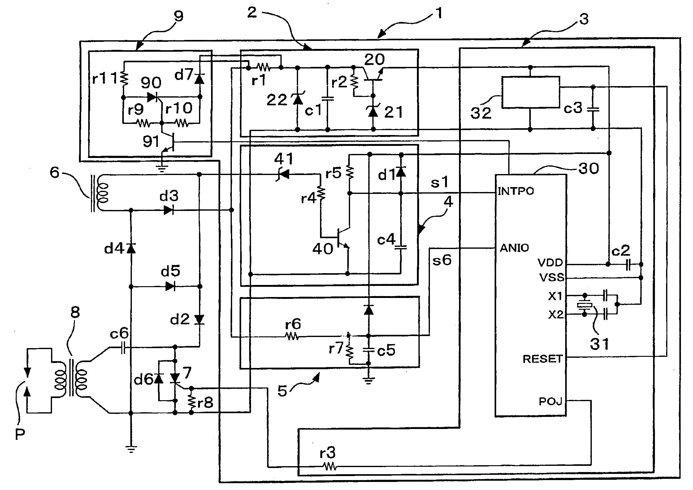
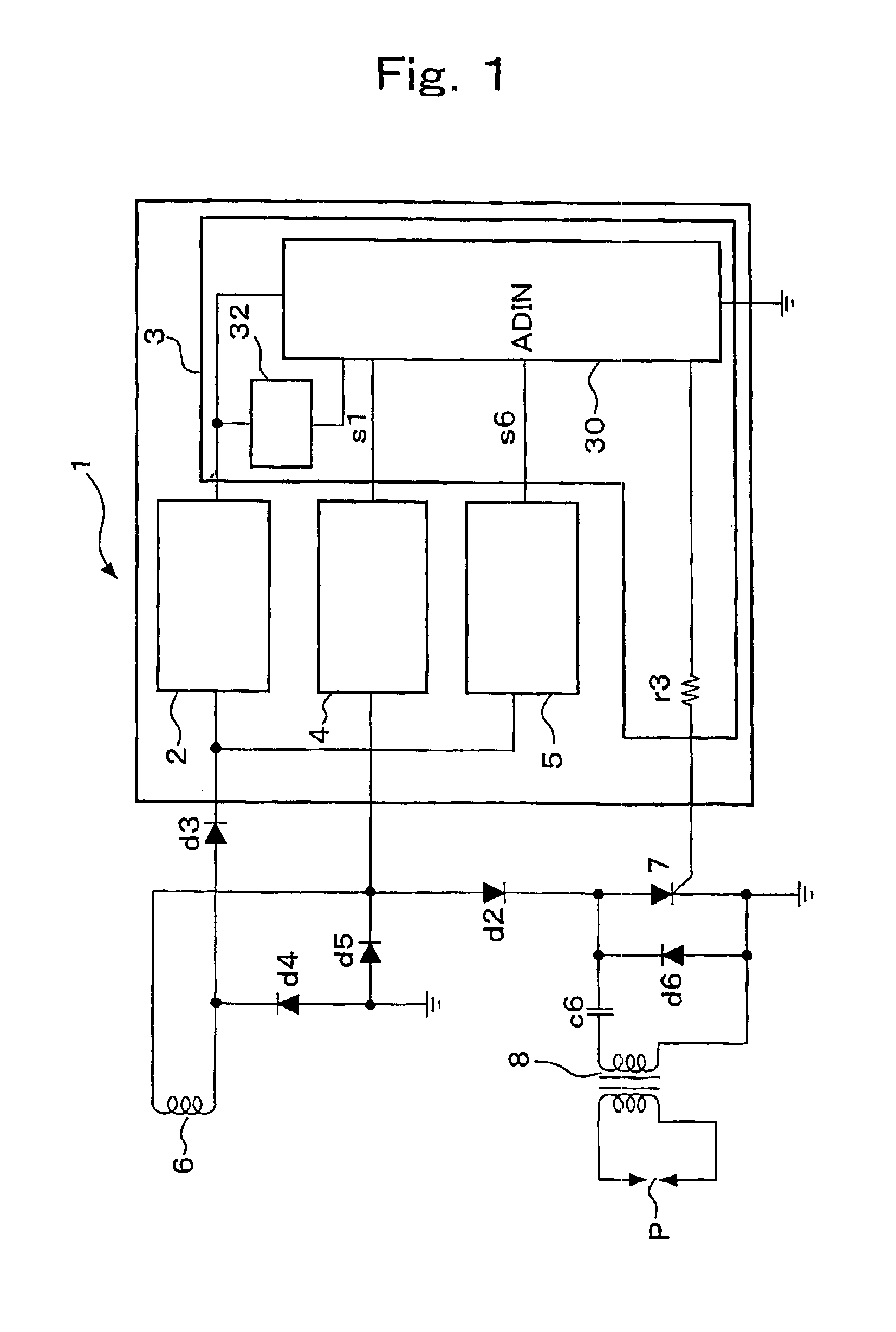
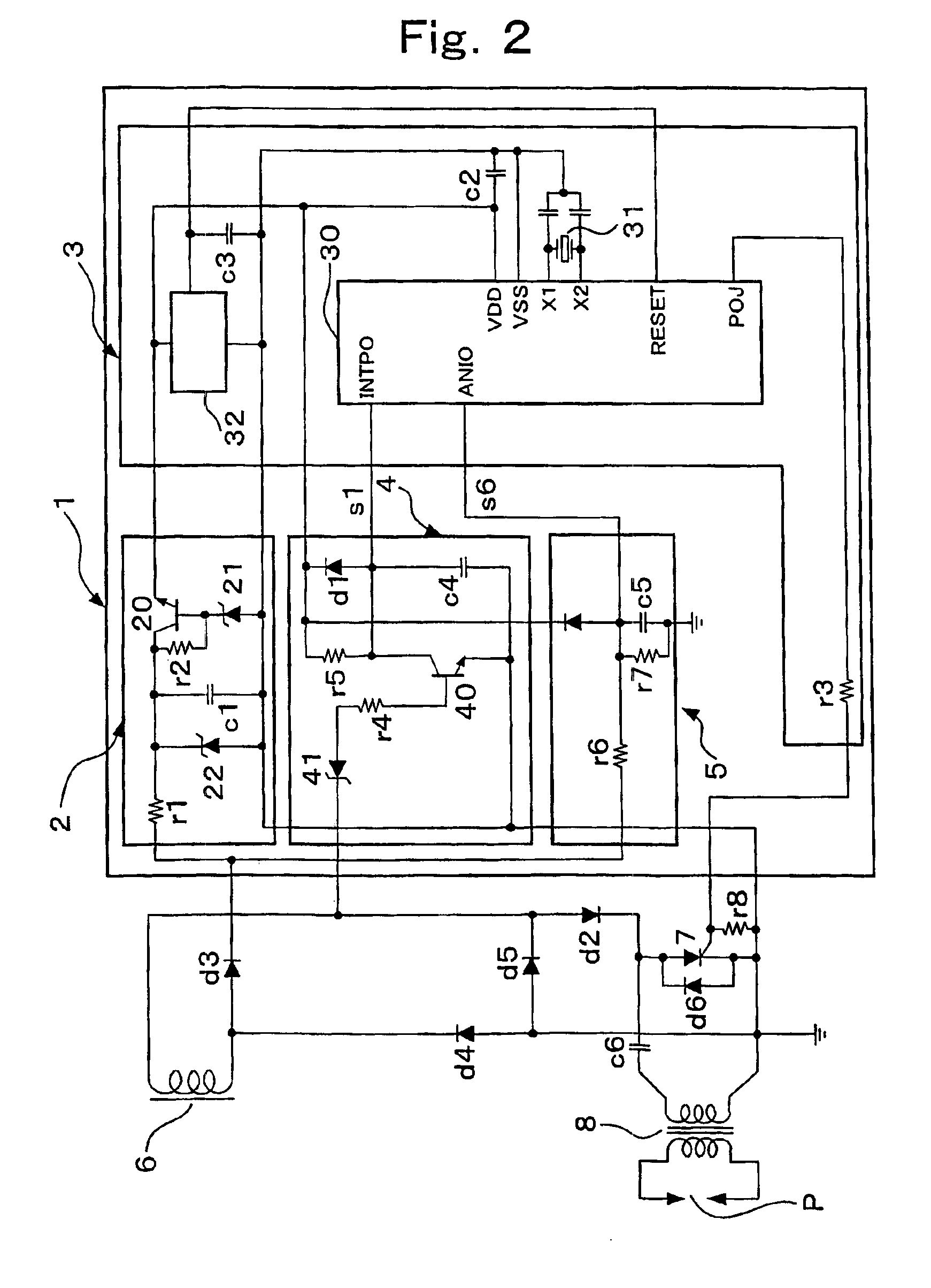
[0124]FIG. 1 is a block circuit diagram illustrating a basic circuit configuration of an ignition timing control device 1 according to the present invention, the ignition timing control device 1 constituting an ignition device for an internal combustion engine in combination with a capacitive discharge ignition circuit. The ignition timing control device 1 includes a constant voltage power supply portion 2, a microcomputer portion 3, a cycle signal generation portion 4, and a voltage detection portion 5, each of the components being detailed in FIG. 2.

[0125]The capacitive discharge ignition circuit incorporating the ignition timing control device 1 includes an ignition coil 8 having an ignition plug P connected to a secondary side, a generator coil 6 constituting a high-voltage magneto generator driven by the internal combustion engine, a rechargeab...


PUM


Abstract

The invention simplifies the structure of a magneto generator and stabilizes the operation of an internal combustion engine at the time of start-up, thereby providing an ignition device simplified in structure and reduced in size and providing improved safety to the internal combustion engine. In an ignition device for a capacitive discharge internal combustion engine, an ignition timing signal is calculated with a cycle detection signal obtained at a timing at which a forward voltage portion of an output voltage from a generator coil has reached a cycle detection voltage for making continual ignition operations available, and a peak voltage detection signal and a start-up voltage detection signal are obtained in accordance with a delayed reverse voltage portion of the output voltage from the generator coil. In a preset normal region speed or less in which a load is coupled to the engine, an ignition signal is output immediately after the peak voltage detection signal has been generated. In a normal region speed or more, an ignition signal is output after the duration of the ignition timing signal from the point in time of output of the cycle detection signal. At the time of start-up, an ignition signal is output in response to the start-up voltage detection signal according to the cycle detection signal. This eliminates the need of a coil for generating a timing signal and provides a safe start-up operation.

Description

BACKGROUND OF THE INVENTION[0001]1. Field of the Invention[0002]The present invention relates to an ignition device for an internal combustion engine, and more particularly to a method and device for controlling the ignition timing of a capacitive discharge ignition device.[0003]2. Description of the Related Art[0004]A strong demand exists for providing an accurately controlled ignition timing at a desired point in time to provide safe and efficient operations, reduced fuel consumption, and clean exhaust gases for an internal combustion engine. To this end, as disclosed in Japanese Published Examined Patent Application No. H-7-26602, the ignition timing is controlled using a microcomputer.[0005]The aforementioned conventional technique is designed to provide a power supply circuit for converting an output voltage from a generator coil (exciter coil) into a direct voltage so as to employ the power supply circuit as a power supply for the microcomputer. During a low speed operation of...

Claims


Application Information

Patent Timeline
Patent Type & Authority Patents(United States)
IPC IPC(8): F02P1/00F02P1/08F02P3/08F02P5/15F02P9/00
CPCF02P1/086F02P5/1558F02P11/025F02N2250/04F02P5/1506F02P5/1508F02P7/067F02P9/005Y02T10/46Y02T10/40F02P3/04
Inventor YAMASHITA, RYOHEI
Owner IIDA ELECTRIC IND
Why Eureka
Try Eureka