Compensation for low drop out voltage regulator

a voltage regulator and low drop out technology, applied in the field of voltage regulator compensation, can solve the problems of high gain bandwidth, unstable feedback loop, and requires a relatively high current, and achieve the effects of high gain, reduced input voltage, and reduced input voltag

Active Publication Date: 2005-12-20
MARVELL ASIA PTE LTD
View PDF8 Cites 96 Cited by
  • Summary
  • Abstract
  • Description
  • Claims
  • Application Information

AI Technical Summary

Benefits of technology

[0023]As in the Miller compensation case, AC coupling capacitor Ca introduces a zero at zero frequency. There are also poles and zeros in driver amplifier 20 that should be placed at very high frequencies. To make inner loop 30 stable, parasitic capacitance Cp cannot be very small, as it is used to cancel the AC-coupling zero. If Cp is small, inne

Problems solved by technology

A phase margin of a feedback loop including error amplifier 12, transistor 14, and voltage divider R1 and R2 can become negative when other parasitic poles are close to two low frequency poles, which may cause the feedback loop to be unstable.
This gain bandwidth is very high and requires a relatively high current in the error amplifier and/or buffer between it and the pass device.
However, it is difficult to design a high gain, low impedance driver amplifier

Method used


Image

  • Compensation for low drop out voltage regulator
  • Compensation for low drop out voltage regulator
  • Compensation for low drop out voltage regulator

Examples


Embodiment Construction

[0038]The following description of the preferred embodiment(s) is merely exemplary in nature and is in no way intended to limit the invention, its application, or uses.

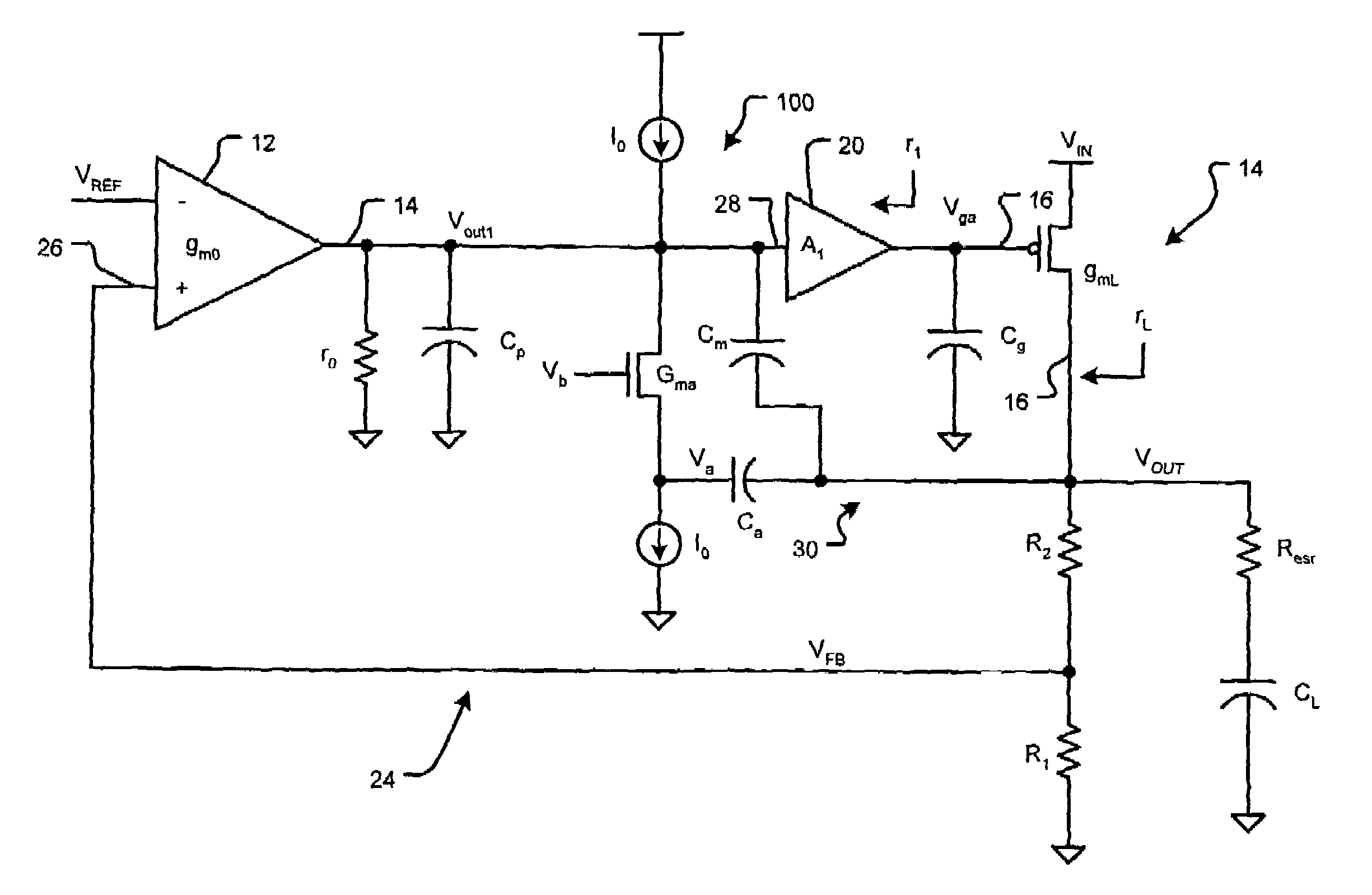
[0039]As used herein, “Miller effect” refers to the use of feedback capacitance to lower an input pole frequency. “Miller compensation” refers to a feedback topology in which a “Miller feedback capacitor” (or “Miller capacitor”) provides feedback to the input of an amplifier from a later stage, such as the output of the amplifier, or the output of the amplifier as further buffered and / or amplified. Miller compensation makes a system's open loop transfer function approximate simple first order dynamics over a wide range by creating a dominant pole.

[0040]As used herein, an “Ahuja compensation circuit” refers to a feedback topology that includes an “Ahuja feedback capacitor” (or “Ahuja capacitor”) providing feedback to the input of an amplifier from a later stage, such as the output of the amplifier or the output as furt...


PUM


Abstract

A voltage regulator apparatus includes an error amplifier that amplifies a voltage difference between a reference and a sampled output voltage of the voltage regulator apparatus. A driver amplifier has an input that is responsive to the amplified voltage difference to produce a gate driving voltage at its output. An output transistor having a drain, a gate, and a source is also included. The gate is responsive to the gate driving voltage to produce a regulated output voltage at the source. To stabilize the voltage regulator apparatus, a Miller compensation capacitor is provided to feed a sample of the regulated output voltage back to the input of the driver amplifier; and additionally, an Ahuja compensation circuit is provided to feed back a portion of the regulated output voltage back to the input of the driver amplifier.

Description

CROSS-REFERENCE TO RELATED APPLICATIONS[0001]This application claims the benefit of U.S. Provisional Application Ser. No. 60 / 436,079, filed on Dec. 23, 2002, which is hereby incorporated by reference in its entirety.FIELD OF THE INVENTION[0002]The present invention relates to voltage regulators, and more particularly to compensation for voltage regulators.BACKGROUND OF THE INVENTION[0003]Referring now to FIG. 1, a low drop-out (LDO) voltage regulator 10 includes an error amplifier 12, a transistor 14, and a voltage divider including resistors R1, R2. An output voltage of voltage regulator 10 is controlled by a feedback connection VFB. A reference voltage VREF and a resistive ratio of resistors R1 and R2 determine the value of the output voltage. Transistor 14 may be a PMOS transistor, which provides the required load current.[0004]A minimum permissible drop out voltage defines the maximum efficiency of the voltage regulator 10. The minimum drop out voltage of voltage regulator 10 is...

Claims


Application Information

Patent Timeline
IPC IPC(8): G05F1/56G05F1/575
CPCG05F1/575
Inventor ZHANG, HONGZHANG, JIANCHENGSUTARDJA, SEHAT
Owner MARVELL ASIA PTE LTD
Why Eureka
Try Eureka