Formation-based interpretation of NMR data for carbonate reservoirs

a technology of nmr data and carbonate, which is applied in the direction of instruments, nmr measurement, borehole/well accessories, etc., can solve the problems of poor signal-to-noise ratio (snr), distortion of partial porosity distribution, and poor resolution of nmr data in time domain

Inactive Publication Date: 2005-12-20
BAKER HUGHES INC
View PDF22 Cites 20 Cited by
  • Summary
  • Abstract
  • Description
  • Claims
  • Application Information

AI Technical Summary

Problems solved by technology

Effective porosities are typically summations of partial porosities; however, distortion of partial porosity distributions has been commonly observed for a variety of reasons.
These reasons include poor signal-to-noise ratio (SNR), and poor resolution in the time domain of the NMR data.
Rig time is expensive, so that the general objective in wireline logging is to obtain interpretable data within as short a time as possible.
In contrast, measurements made with a drilling assembly in the wellbore have several problems.
First of all, there is little a priori information available about the actual subsurface formations except that inferred from surface seismic data.
This makes it difficult, if not impossible, to base an acquisition scheme on the basis of expected properties of formations.
Secondly, when the drilling assembly is in a borehole, data communication capability is in most cases severely limited.
The data rate with mud pulsing is limited to a few bits per second and communication through the drillstring becomes a serious problem when the drillbit is being operated due to the vibration and noise produced.
This makes it impossible to evaluate acquired data at the surface and to modify the acquisition scheme based on this evaluation.
A third problem arises from the nature of NMR data itself.
This results in a severe degradation of the data.
As a result, the pore space in sandstones is mainly intergranular and its complexity depends on the degree of sorting.
This distribution results in wide permeability variations for the same total porosity, making it difficult to predict their producibility.
In many carbonates, it is not possible to map the rock texture using conventional logs.

Method used


Image

  • Formation-based interpretation of NMR data for carbonate reservoirs
  • Formation-based interpretation of NMR data for carbonate reservoirs
  • Formation-based interpretation of NMR data for carbonate reservoirs

Examples


Embodiment Construction

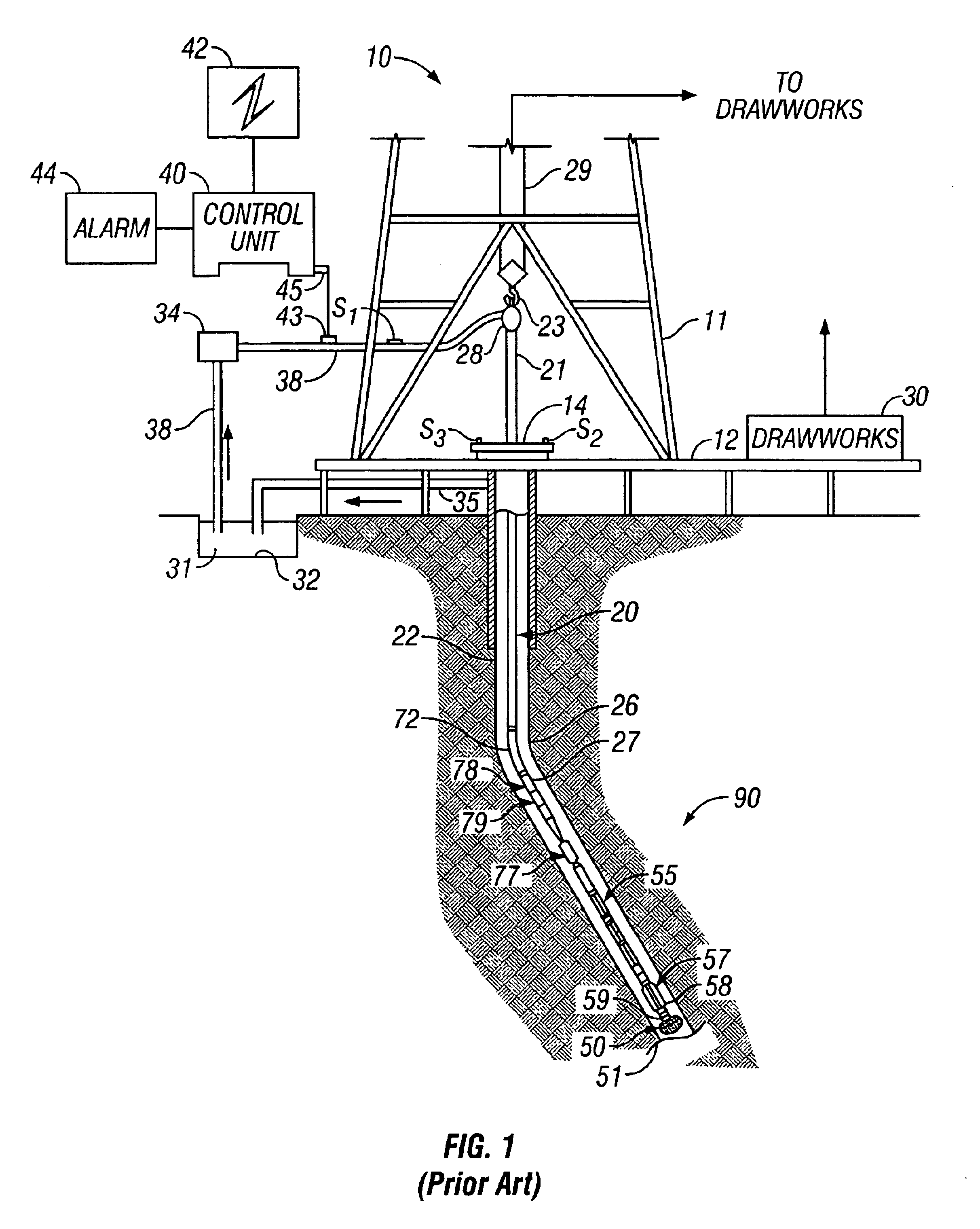
[0043]FIG. 1 shows a schematic diagram of a drilling system 10 with a drillstring 20 carrying a drilling assembly 90 (also referred to as the bottom hole assembly, or “BHA”) conveyed in a “wellbore” or “borehole”26 for drilling the wellbore. The drilling system 10 includes a conventional derrick 11 erected on a floor 12 which supports a rotary table 14 that is rotated by a prime mover such as an electric motor (not shown) at a desired rotational speed. The drillstring 20 includes a tubing such as a drill pipe 22 or a coiled-tubing extending downward from the surface into the borehole 26. The drillstring 20 is pushed into the wellbore 26 when a drill pipe 22 is used as the tubing. For coiled-tubing applications, a tubing injector, such as an injector (not shown), however, is used to move the tubing from a source thereof, such as a reel (not shown), to the wellbore 26. The drill bit 50 attached to the end of the drillstring breaks up the geological formations when it is rotated to dri...


PUM

PropertyMeasurementUnit
sizeaaaaaaaaaa
sizeaaaaaaaaaa
particle sizeaaaaaaaaaa

Abstract

An apparatus and method for determining a parameter of interest of a formation composed of carbonate rock. A nuclear magnetic resonance (NMR) sensor assembly produces a pulsed RF field designed for obtaining measurements indicative of the parameter of interest of the formation. A downhole processor processes the measurements for obtaining BVI and BVM using a cutoff time based on classification of the carbonate. Further processing is done to estimate the permeability of the carbonate.

Description

CROSS REFERENCES TO RELATED APPLICATIONS[0001]This application is a Continuation-in-part of U.S. patent application Ser. No. 09 / 928,768 filed on Aug. 13, 2001 now U.S. Pat. No. 6,727,696, which is a Continuation in part of U.S. patent application Ser. No. 09 / 839,423 filed on Apr. 20, 2001, now U.S. Pat. No. 6,446,736, which is a continuation of U.S. patent application Ser. No. 09 / 247,340 filed on Feb. 9, 1999, now U.S. Pat. No. 6,247,542.BACKGROUND OF THE INVENTION[0002]1. Field of the Invention[0003]This invention is related to methods for acquiring and processing nuclear magnetic resonance (NMR) measurements for determination of longitudinal and transverse relaxation times T1 and T2 and related petrophysical properties. Specifically, the invention deals with use of an expert system downhole for acquiring and evaluating NMR measurements contemporaneous with the drilling of wells in a formation including a carbonate rock, and with use of a downlink communication from the surface for...

Claims


Application Information

Patent Timeline
Patent Type & Authority Patents(United States)
IPC IPC(8): E21B33/124E21B41/00E21B43/26E21B49/00E21B49/06E21B49/10G01N3/32G01N15/08G01R33/44G01V3/32
CPCE21B33/1243E21B43/26E21B49/008E21B49/06E21B49/10G01N3/32G01N15/082G01N24/081G01V3/32E21B2041/0028E21B2200/22
Inventor KIESL, CHRISTIANKRUSPE, THOMASTHERN, HOLGER F.SURHOLT, IRIS
Owner BAKER HUGHES INC
Why Eureka
Try Eureka