
Synchronization of interrupts with data packets

Inactive Publication Date: 2005-12-20
MELLANOX TECHNOLOGIES LTD
View PDF11 Cites 103 Cited by
  • Summary
  • Abstract
  • Description
  • Claims
  • Application Information

AI Technical Summary

Benefits of technology

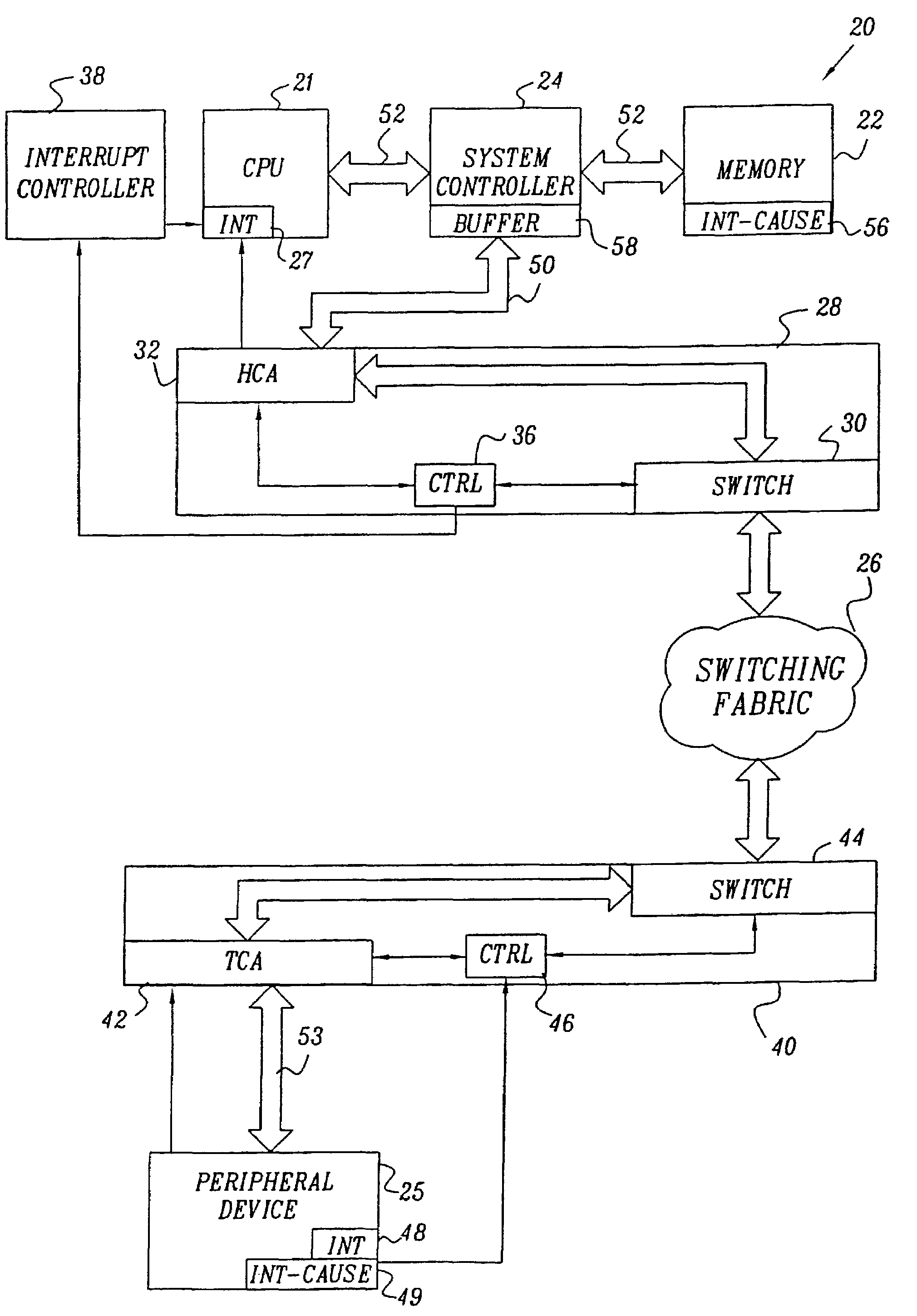
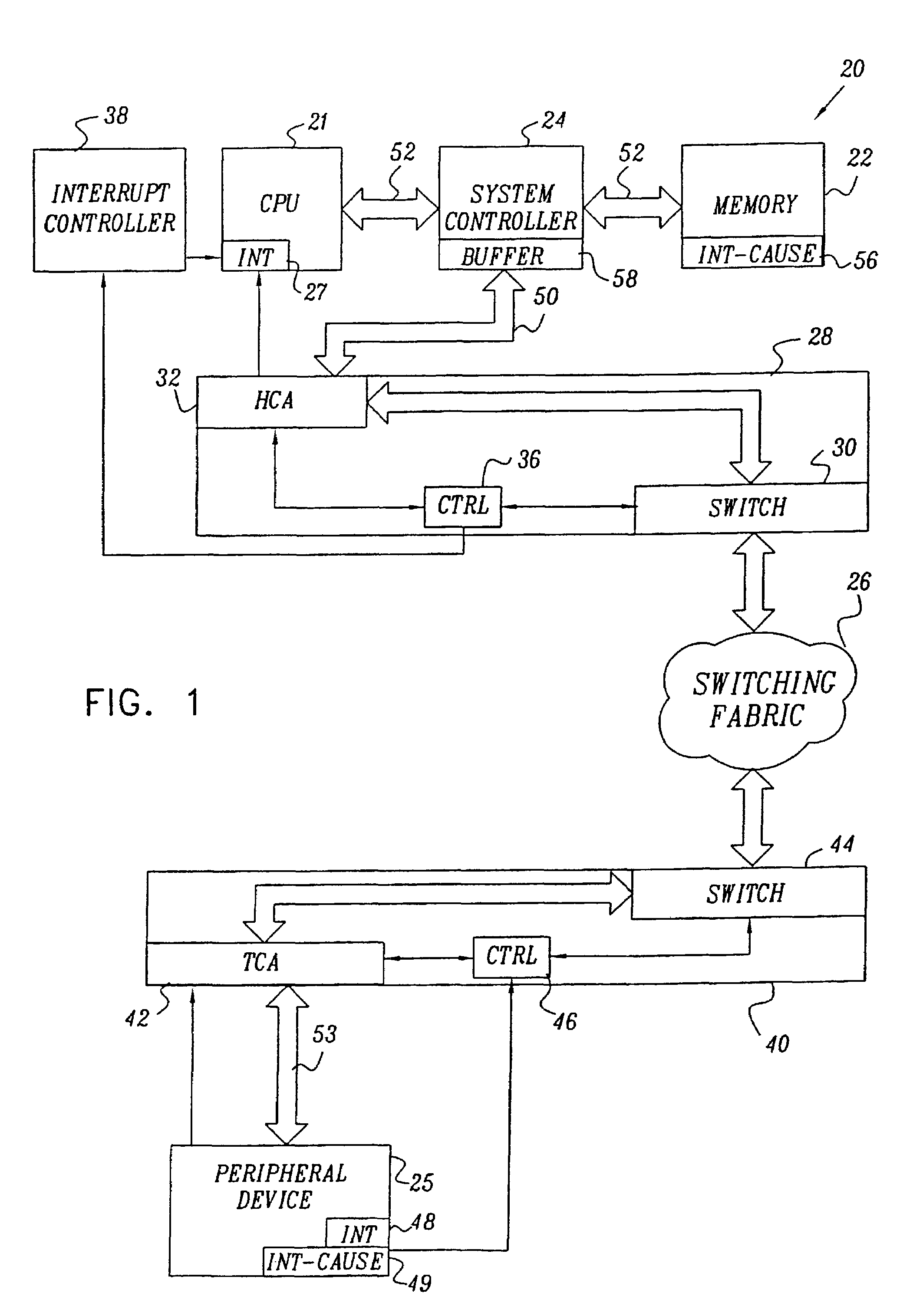
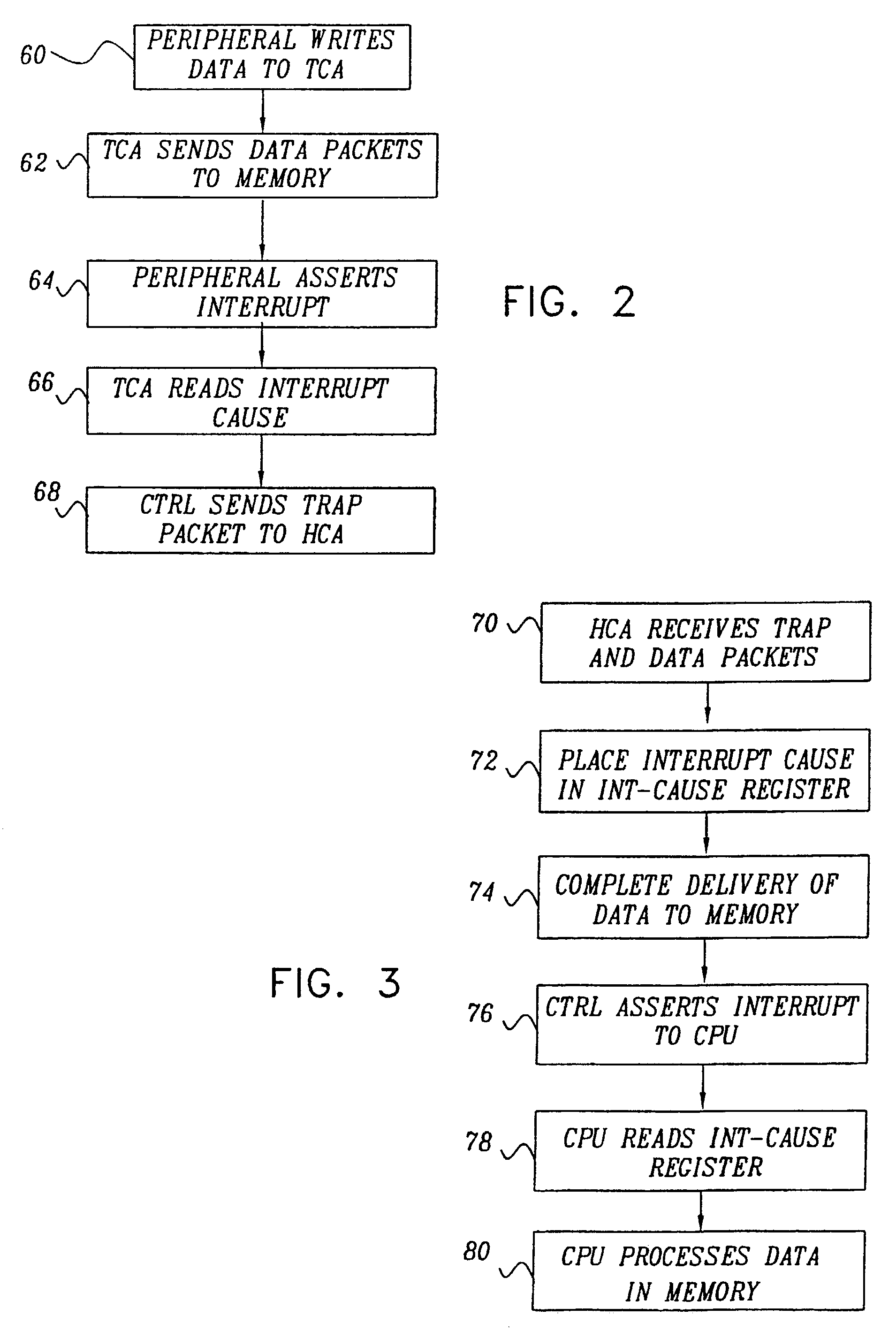
[0009]It is an object of the present invention to provide an improved method and system for passing data packets and associated interrupts through a switching fabric.
[0010]It is a further object of some aspects of the present invention to provide a method and system for communication between a CPU and peripheral devices via a switching fabric that ensures proper synchronization between data and interrupts transmitted over the fabric.
[0011]It is still a further object of some aspects of the present invention to provide a method and system for communication between a CPU and peripheral devices via a switching fabric that reduces latency and processing time required for servicing of interrupts by the CPU.
[0012]In preferred embodiments of the present invention, a CPU and a peripheral device are linked to a packet-switching fabric by respective host and target network interfaces. The target interface receives data over a local bus from the peripheral device, for transmission in the form of packets to a system memory associated with the CPU. After sending the data, the peripheral device asserts an interrupt. The interrupt from the device is connected to an interrupt input of the target interface, rather than directly to the CPU or to a central system controller, as in systems known in the art. In response to the interrupt, the target interface reads the interrupt cause from the peripheral device, and then sends a special interrupt packet, including the interrupt cause, to the host interface. Preferably, the target interface sends the interrupt packet on the same channel as it sent the data packets, i.e., over the same “virtual lane,” or route, and with the same priority as the data packets. It thus assures that the host interface will receive the interrupt packet only after it has received all of the preceding data packets.
[0013]Upon receiving the interrupt packet, the host interface places the interrupt cause in a predefined register in the memory. An interrupt signal is then sent from the host interface to an interrupt input of the CPU. Upon receiving the signal, the CPU checks to ensure that the host interface has finished writing all of the data from the peripheral device to the memory. This check serves a similar purpose to the configuration read described in the Background of the Invention. Only after completing the check does the CPU read the interrupt cause and begin processing the data in the memory. The CPU performs all of these steps locally, communicating with the host interface and memory over a local system bus, with latency on the order of nanoseconds, rather than having to exchange messages with the peripheral device through the switching fabric, taking many microseconds. As a result, interrupt response latency is minimized, and the CPU does not waste precious time and resources waiting for the configuration read response.

Problems solved by technology

As data path-widths grow, and clock speeds become faster, however, the parallel bus is becoming too costly and complex to keep up with system demands.
Therefore, there is no a priori assurance that all of the data will have been written to the memory before the CPU begins reading.
The “race” between the interrupt path and the data path can result in errors (as when a CPU read stalls the data).
This scheme has a number of serious performance drawbacks, however.
The exchange adds substantial latency—typically 10 microseconds or more—every time the CPU must service an interrupt.
Furthermore, since configuration reads are used as synchronization barriers, the CPU is stalled from the moment the configuration read request is issued until its response has arrived.
Valuable CPU time is therefore wasted waiting for the interrupt cause to be retrieved.

Method used


Image

  • Synchronization of interrupts with data packets
  • Synchronization of interrupts with data packets
  • Synchronization of interrupts with data packets

Examples


Embodiment Construction

[0040]FIG. 1 is a block diagram that schematically illustrates a computing system 20 built around a switching fabric 26, in accordance with a preferred embodiment of the present invention. The switching fabric preferably comprises an InfiniBand fabric, as described in the Background of the Invention, and some of the terms used hereinbelow are specific to the InfiniBand architecture. It will be understood, however, that the system architecture and methods of communication described herein are in no way limited to InfiniBand, and that other switching fabrics, as are known in the art, may be configured to handle and convey interrupts in a similar manner.

[0041]A CPU 21 is coupled to communicate via a system bus 52 with a system controller 24 and a system memory 22, as is known in the art. Typically (although not necessarily), the CPU comprises an Intel Pentium processor, and bus 52 is a proprietary bus used in conjunction with this processor, System controller 24 is coupled to a standar...


PUM


Abstract

A method and apparatus for conveying data over a packet-switching network (26). Data are received from a peripheral device (25) for transmission via the network to a memory (22) associated with a central processing unit (CPU) (21), followed by an interrupt signal from the peripheral device associated with the data. One or more data packets containing the data are sent over the network to a host network interface (32) serving the memory and the CPU, followed by an interrupt packet sent over the network to the host network interface. Responsive to the interrupt packet, an interrupt input of the CPU is asserted only after the one or more data packets have arrived at the host network interface.

Description

CROSS-REFERENCE TO RELATED APPLICATION[0001]This is a continuation in part of application Ser. No. 09 / 559,352, filed Apr. 27, 2000, now U.S. Pat. No. 6,243,787. This application claims the benefit of U.S. Provisional Patent Application 60 / 152,849, filed Sep. 8, 1999, and of U.S. Provisional Patent Application 60 / 175,339, filed Jan. 10, 2000. Both of these co-pending applications are assigned to the assignee of the present patent application and are incorporated herein by reference.FIELD OF THE INVENTION[0002]The present invention relates generally to computing systems, and specifically to systems that use packet-switching fabrics to connect a computer host to peripheral devices.BACKGROUND OF THE INVENTION[0003]In current-generation computers, the central processing unit (CPU) is connected to the system memory and to peripheral devices by a parallel bus, such as the ubiquitous Peripheral Component Interface (PCI) bus. As data path-widths grow, and clock speeds become faster, however,...

Claims


Application Information

Patent Timeline
IPC IPC(8): H04L1/00H04L12/24H04L12/40H04L12/46H04L12/56H04L12/66
CPCH04L1/0063H04L12/4604H04L12/4625H04L12/66H04L41/0213H04L41/06H04L2001/0092
Inventor KAGAN, MICHAELCRUPNICOFF, DIEGOGABBAY, FREDDYROTTENBERG, SHIMON
Owner MELLANOX TECHNOLOGIES LTD
Learn More