Sensor system and method for sensing in an elevated-temperature environment, with protection against external heating

Active Publication Date: 2005-12-27
RAYTHEON CO
View PDF31 Cites 2 Cited by
  • Summary
  • Abstract
  • Description
  • Claims
  • Application Information

AI Technical Summary

Benefits of technology

[0015]The present sensor system uses an external thermal-insulation layer that is compatible with the forces experienced in high-speed flight conditions, and also provides good insulation for the sensor unit from the temperatures experienced under these conditions. The sensor system may be implemented in any size of the sensor housing and total weight, but it is most beneficially applied when the sensor housing must be small, with a tightly constrained size envelope, and the total weight of the sensor housing and sensor unit must be small. The use of an interior insulation would require an increase in

Problems solved by technology

However, all cryogenic coolers are limited in heat removal rate and in temperature differential.
Cryocooler operation is handicapped and may become impossible as the heat load and external temperature increase.
Additionally, and very importantly, the overall physical size (“envelope”) of the sensor system must be maintained very small, because the sensor system is usually positioned on the aircraft at a location with an unobstructed view of the intended field of view, but which also has very little space available due to the aircraft's geometry and/or

Method used


Image

  • Sensor system and method for sensing in an elevated-temperature environment, with protection against external heating
  • Sensor system and method for sensing in an elevated-temperature environment, with protection against external heating
  • Sensor system and method for sensing in an elevated-temperature environment, with protection against external heating

Examples


Embodiment Construction

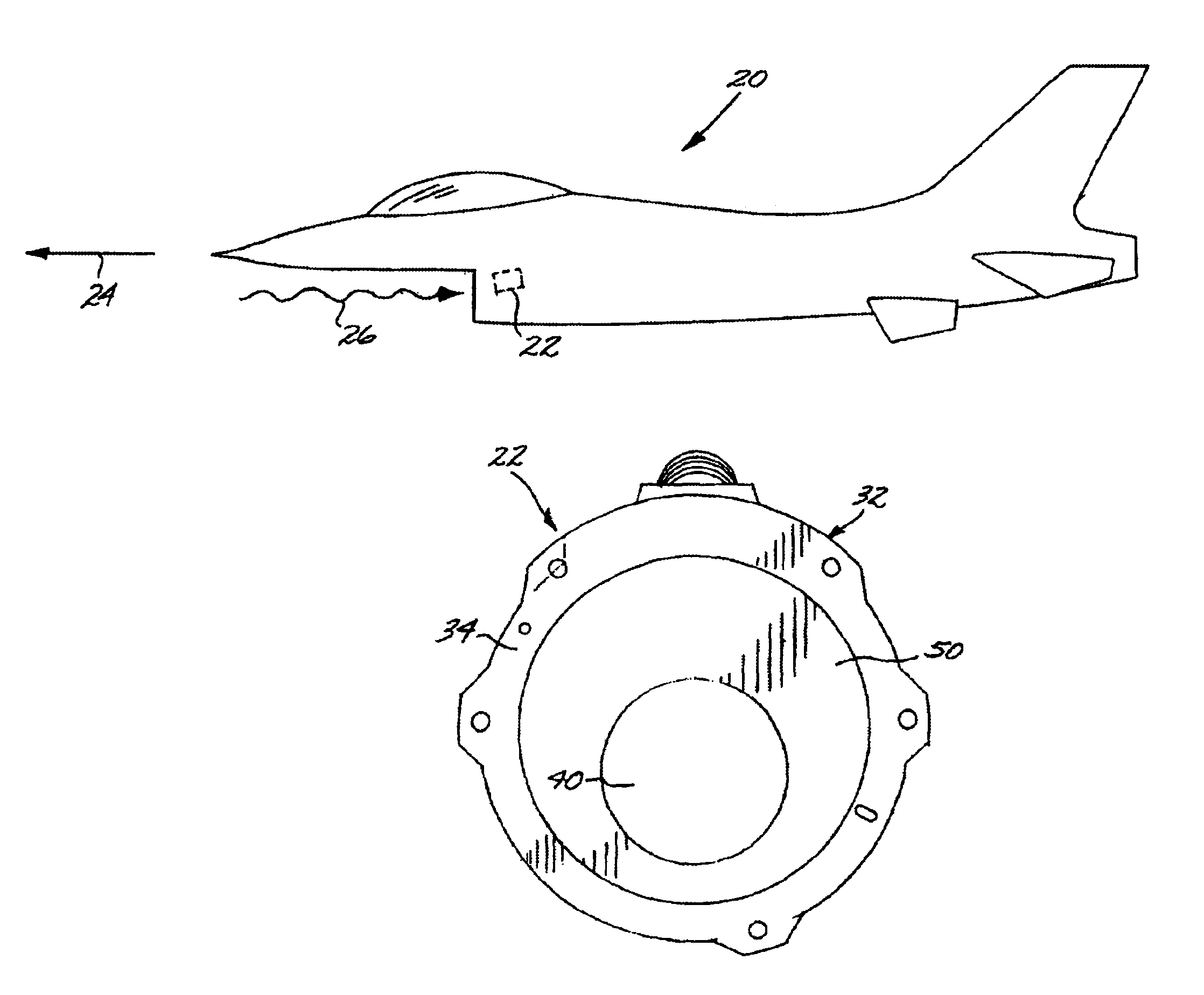
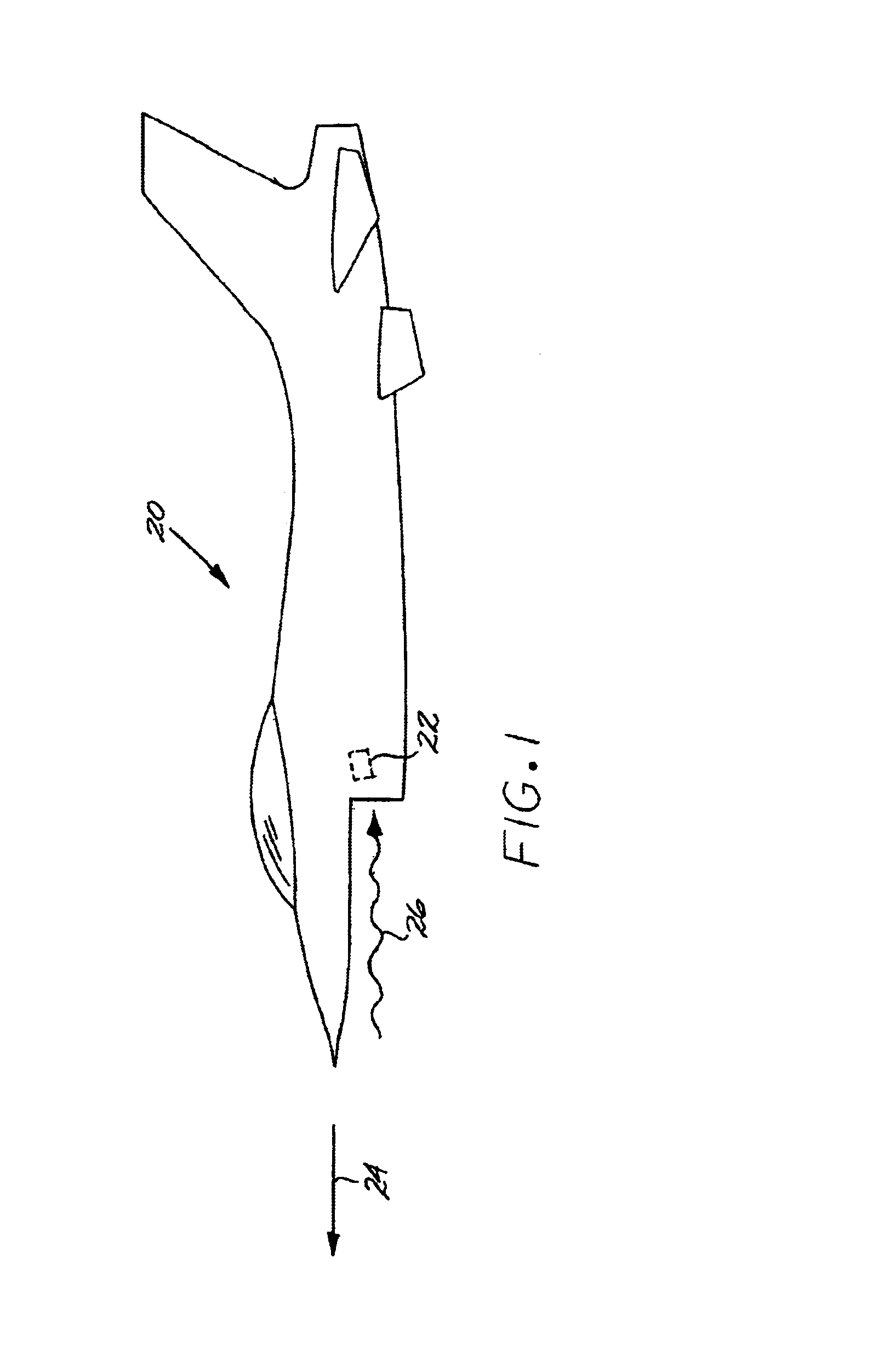
[0022]FIG. 1 schematically depicts an aircraft 20 (with the wing not shown so as not to obscure pertinent structure), and a preferred embodiment of a sensor system 22 affixed to the aircraft 20. The aircraft 20 flies in a direction of flight 24. The aircraft 20 may be a manned aircraft or an unmanned aircraft such as a missile. The aircraft 20 may be a military or a civilian aircraft. No limitation is known on the types of aircraft 20 that may be used. In the embodiment of FIG. 1, the sensor system 22 is fixed in a forward-facing orientation. That is, the sensor system 22 faces in the direction of flight 24 of the aircraft 20, so that it receives an input signal 26 generally from ahead of the aircraft 20.

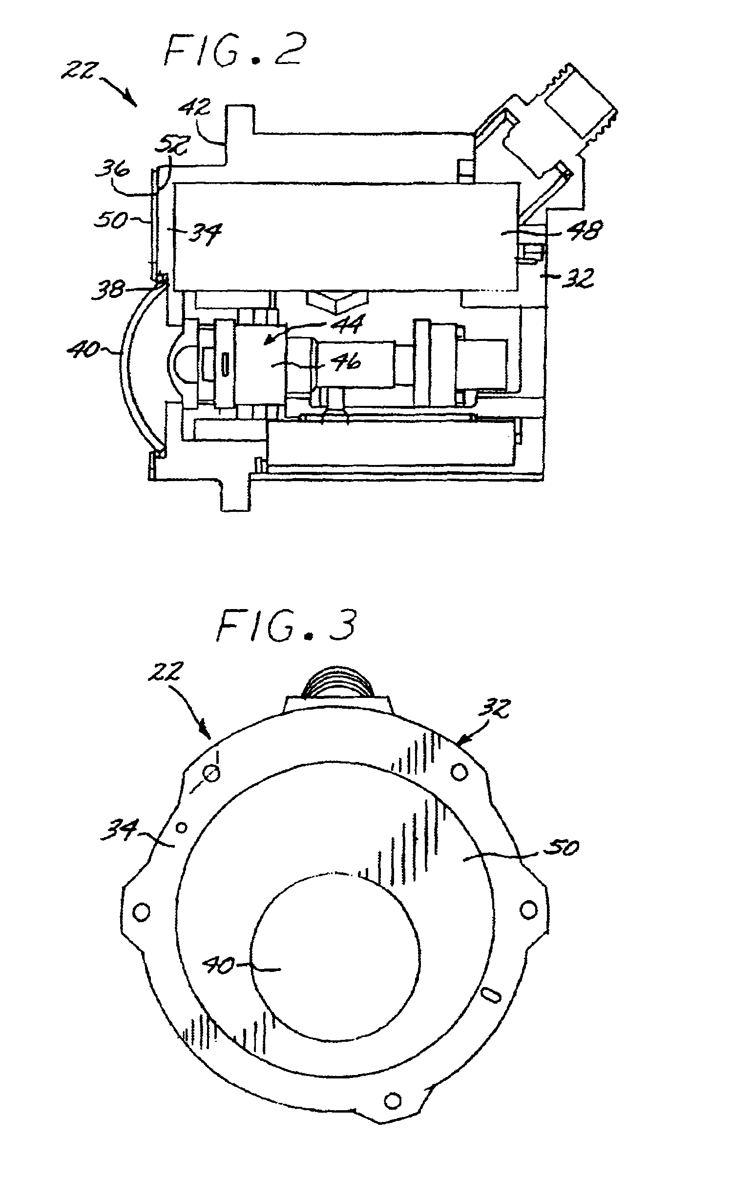
[0023]FIGS. 2–4 illustrate the sensor system 22 in greater detail and in various views. The sensor system 22 is comprised largely of a sensor housing 30 having an exterior wall 32 that both supports and protects the internal components. The exterior wall 32 extends around most of th...


PUM


Abstract

Sensing in an elevated-temperature environment is provided using a sensor system having a sensor housing with an exterior wall with a window-support region having an outwardly facing external face, and a window through the window-support region of the exterior wall and affixed to the exterior wall. A sensor unit contained within the sensor housing receives an input signal through the window. A thermal-insulation layer is on the external face of the window-support region of the exterior wall at a location immediately adjacent to the window. The sensor system is operated in an environment wherein the window-support region of the exterior wall is heated to a temperature of greater than about 100° C. in the event that no thermal-insulation layer is present. In a typical application, the sensor system is attached to an aircraft such that the external face is in a forward-facing orientation, and the aircraft is operated such that the external face is heated by aerodynamic heating.

Description

[0001]This invention relates to sensor systems such as infrared sensor systems and more particularly, to a sensor system exposed to elevated temperatures during operation.BACKGROUND OF THE INVENTION[0002]An aircraft typically utilizes a number of sensors of different types. Many military aircraft and an increasing number of civilian aircraft have infrared sensors to detect potential threats such as missiles fired at the aircraft. The infrared sensor senses the presence of an infrared signature, such as that produced by the motor of a missile approaching the aircraft, and provides a warning so that countermeasures may be employed.[0003]In one type of infrared sensor system, the sensor (detector) is operated at a reduced temperature to improve its performance. The reduced temperature may be produced in any manner, but it is typically produced by a small cryocooler that is integral with the sensor system inside its sensor housing. The cryocooler is operable to cool the sensor to temper...

Claims


Application Information

Patent Timeline
IPC IPC(8): G01J1/02G01J5/04
CPCG01J1/02G01J1/0252G01J5/04G01J5/042G01J5/046G01J5/048G01J5/06G01J5/08G01J5/0803G01J5/0875
Inventor WELLMAN, WILLIAM H.BREGANTE, ALDON L.RAVURI, RAO S.
Owner RAYTHEON CO
Why Eureka
Try Eureka