High density MRAM using thermal writing

Active Publication Date: 2005-12-27
COMMISSARIAT A LENERGIE ATOMIQUE ET AUX ENERGIES ALTERNATIVES +1
View PDF5 Cites 94 Cited by
  • Summary
  • Abstract
  • Description
  • Claims
  • Application Information

AI Technical Summary

Benefits of technology

[0017]There may be several advantages to fabricating the magnetic memory cell described herein. In particular, magnetic memory cell junctions may be formed with a reduced surface area, allowing higher density memory cell arrays to be fabricated. In addition, the write selectivity of magnetic memory arrays may be improved by the inclusion of an antiferromagnetic layer within the free magnetic portion of the junction. Consequently, the reliability of the device may be improved. Furthermore, the method described herein to write to a cell including an antiferromagnetic layer within the free magnetic portion of the junction allows the current requirements of the device to be decreased. In some

Problems solved by technology

As explained below, variations within cell junction sizes and shapes, however, may cause the amount of current needed to switch memory cells to vary, reducing the reliability of the device.
In addition, a cell junction configuration including elongated and shortened dimensions may undesirably occupy v

Method used


Image

  • High density MRAM using thermal writing
  • High density MRAM using thermal writing
  • High density MRAM using thermal writing

Examples


Example

[0033]While the invention may include various modifications and alternative forms, specific embodiments thereof are shown by way of example in the drawings and will herein be described in detail. It should be understood, however, that the drawings and detailed description thereto are not intended to limit the invention to the particular form disclosed, but on the contrary, the intention is to cover all modifications, equivalents and alternatives falling within the spirit and scope of the present invention as defined by the appended claims.

DETAILED DESCRIPTION OF PREFERRED EMBODIMENTS

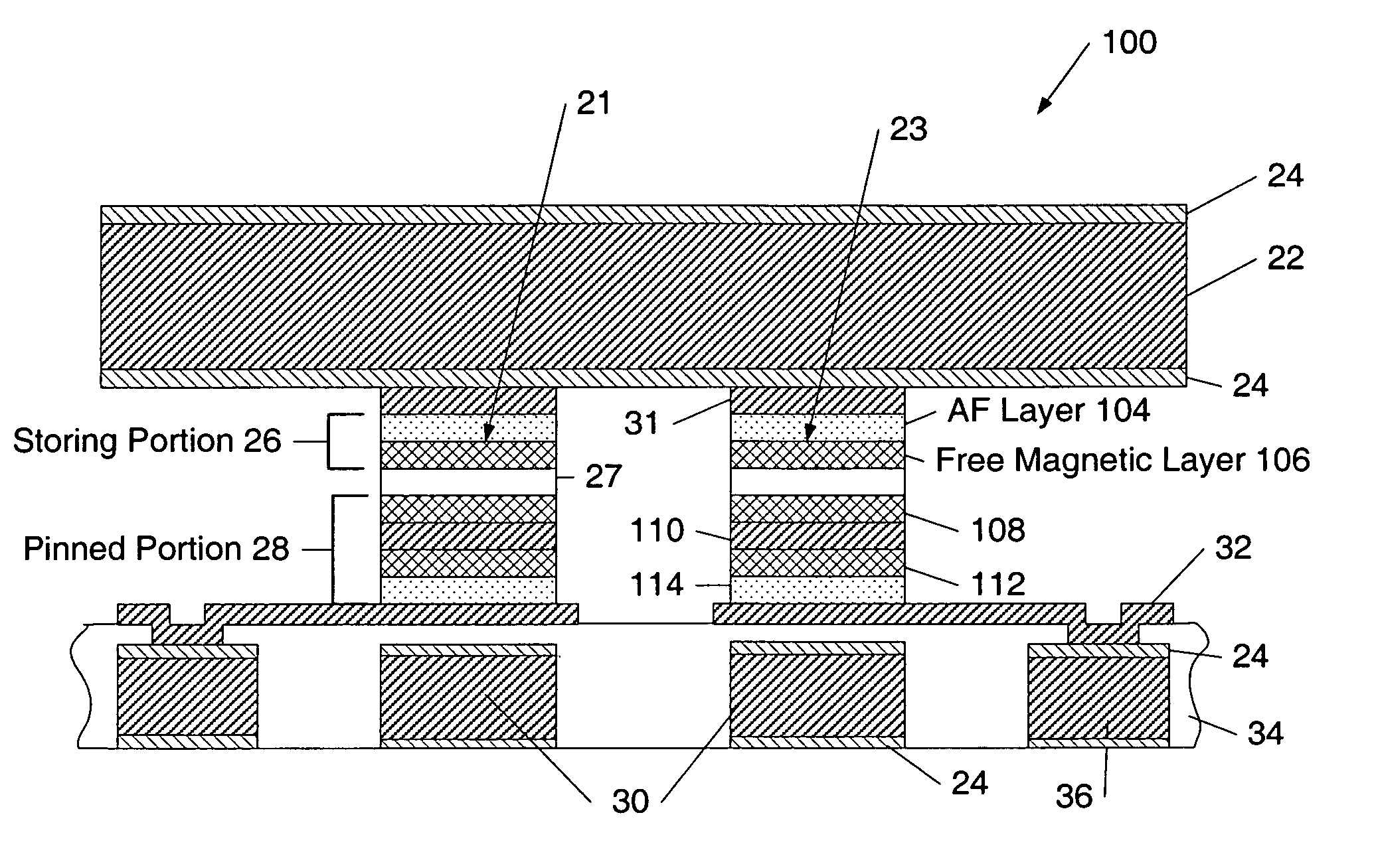
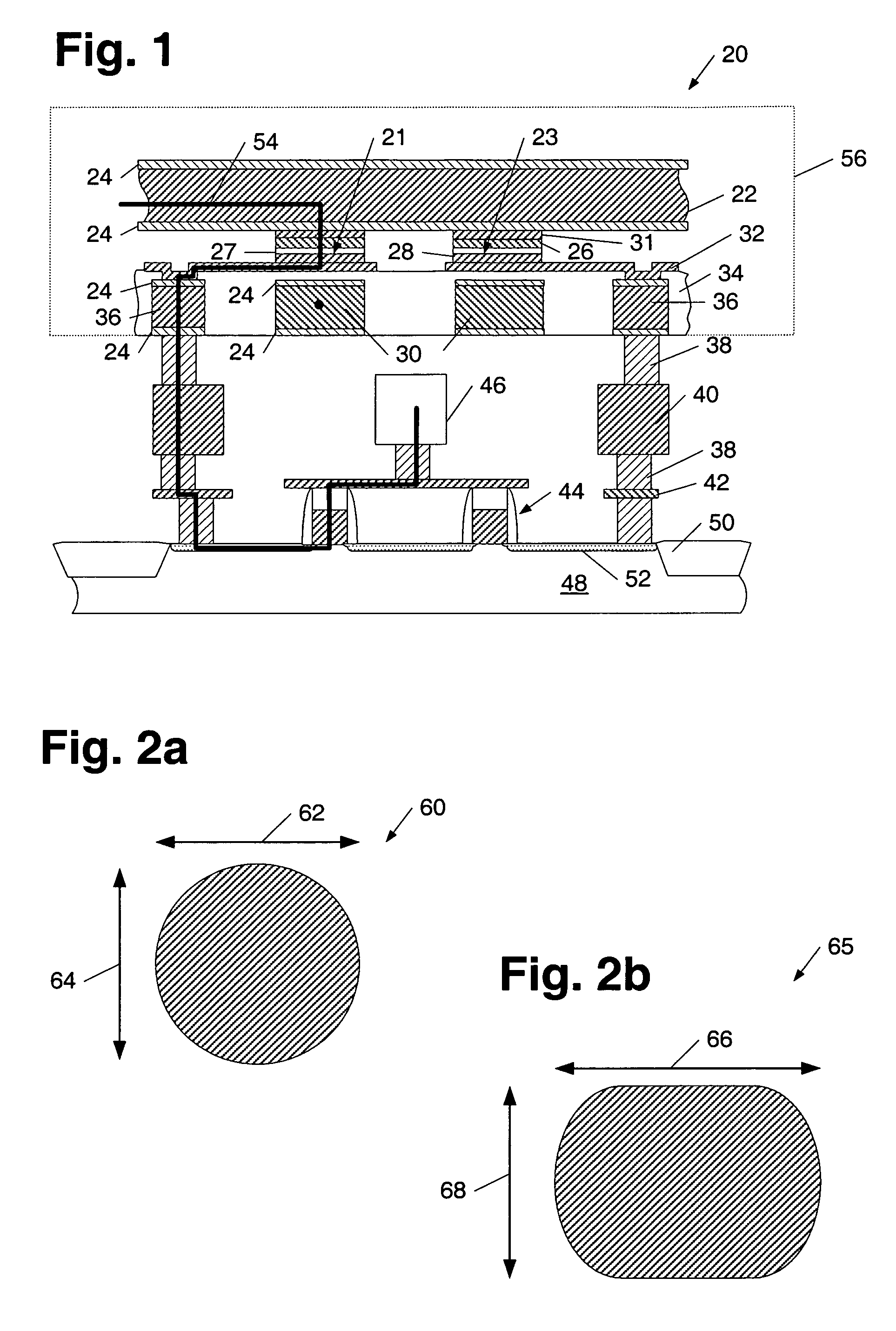
[0034]Turning to the drawings, exemplary embodiments of memory cell array configurations are provided in FIGS. 1 and 6–9. In addition, methods for programming a memory cell having such configurations are described in reference to FIGS. 3–5. FIG. 1 depicts a partial cross-sectional view of memory array 20 which includes magnetic memory cell junctions 21 and 23 interposed between bit line 22 and digit line...


PUM


Abstract

A memory cell includes a magnetic cell junction having an antiferromagnetic layer within a portion of the cell junction that is adapted to characterize a logic state of a bit written to the junction. More specifically, a memory cell includes, an antiferromagnetic layer arranged in contact with an adjacent magnetic layer within a storing portion of a magnetic cell junction. Such a magnetic cell junction configuration and a method for programming a memory cell with such a cell junction configuration may be used to improve the write selectivity of a memory cell array and reduce the amount of current needed to write a bit to a memory cell. Moreover, a memory cell includes a magnetic cell junction having an aspect ratio less than 1.6. In addition, a memory cell includes at least two resistors.

Description

BACKGROUND OF THE INVENTION[0001]1. Field of the Invention[0002]This invention relates to magnetic memory cells and, more particularly, to magnetic memory cell junction compositions and shapes. In addition, the invention relates to a method for programming a memory cell including such junctions.[0003]2. Description of the Related Art[0004]The following descriptions and examples are given as background information only.[0005]Recently, advancements in the use of magnetoresistive materials have progressed the development of magnetic random access memory (MRAM) devices to function as viable non-volatile memory circuits. In general, MRAM circuits exploit the electromagnetic properties of magnetoresistive materials to set and maintain information stored within individual magnetic memory cell junctions of the circuit. In particular, MRAM circuits utilize magnetization direction to store information within a memory cell junction, and differential resistance measurements to read information ...

Claims


Application Information

Patent Timeline
IPC IPC(8): G11C11/14G11C11/15
CPCG11C11/15G11C11/1675
Inventor OUNADJELA, KAMEL
Owner COMMISSARIAT A LENERGIE ATOMIQUE ET AUX ENERGIES ALTERNATIVES
Why Eureka
Try Eureka