Reheat combustion system for a gas turbine

a combustion system and gas turbine technology, applied in mechanical equipment, machines/engines, lighting and heating apparatus, etc., can solve the problems of acoustic liners not being readily accessible, helmholtz resonators not optimal for the frequency range, and the volume of the resonator is not optimal, etc., to achieve good cooling characteristics

Active Publication Date: 2006-01-03
ANSALDO ENERGIA IP UK LTD
View PDF11 Cites 175 Cited by
  • Summary
  • Abstract
  • Description
  • Claims
  • Application Information

AI Technical Summary

Benefits of technology

[0013]The present invention sets out to provide a means for damping high-frequency pulsations for a gas turbine reheat system, whilst providing good cooling characteristics.

Problems solved by technology

Consequently, Helmholtz resonators are normally confined for use in the low frequency range, where the frequency shift between acoustic modes is relatively large (i.e. pressure peaks are well separated) and the resonator volume is also relatively large.
In such a case, classical Helmholtz resonators are not optimal for the frequency range in question.
However, the walls of the burner and combustion chamber must be cooled by means of cold air coming from the compressor and the acoustic liners do not readily facilitate this.

Method used


Image

  • Reheat combustion system for a gas turbine
  • Reheat combustion system for a gas turbine
  • Reheat combustion system for a gas turbine

Examples


Embodiment Construction

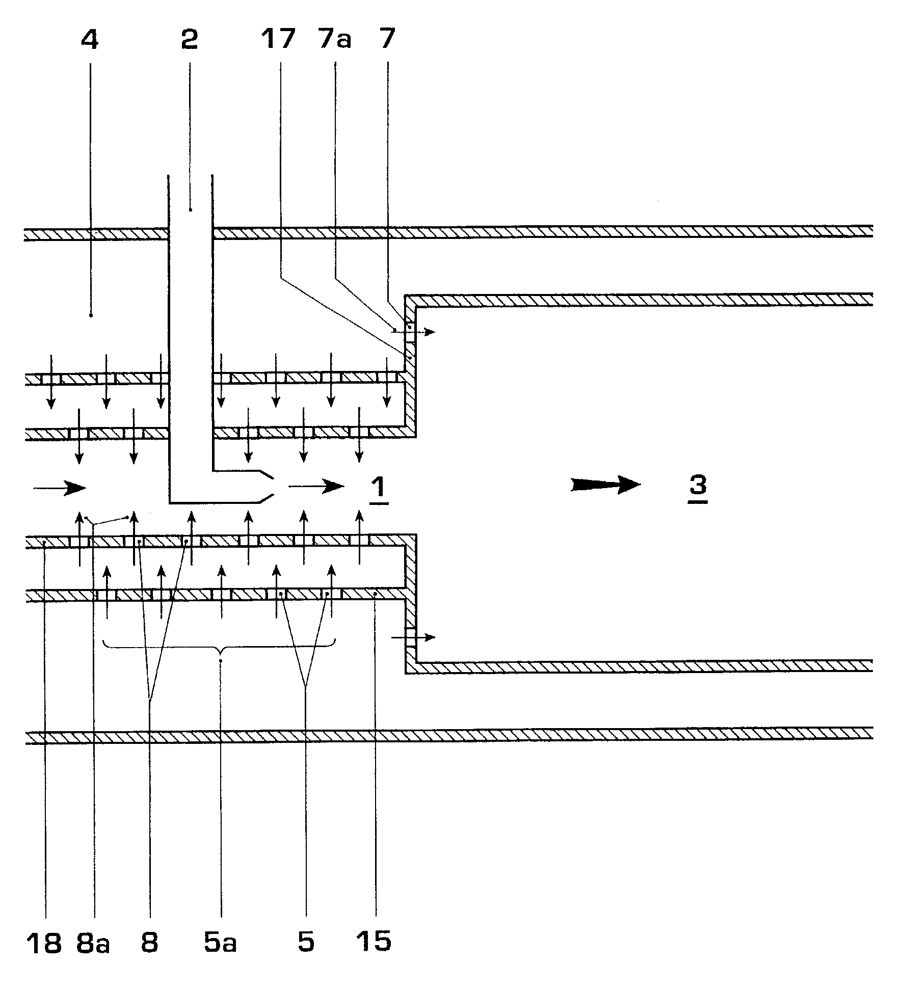
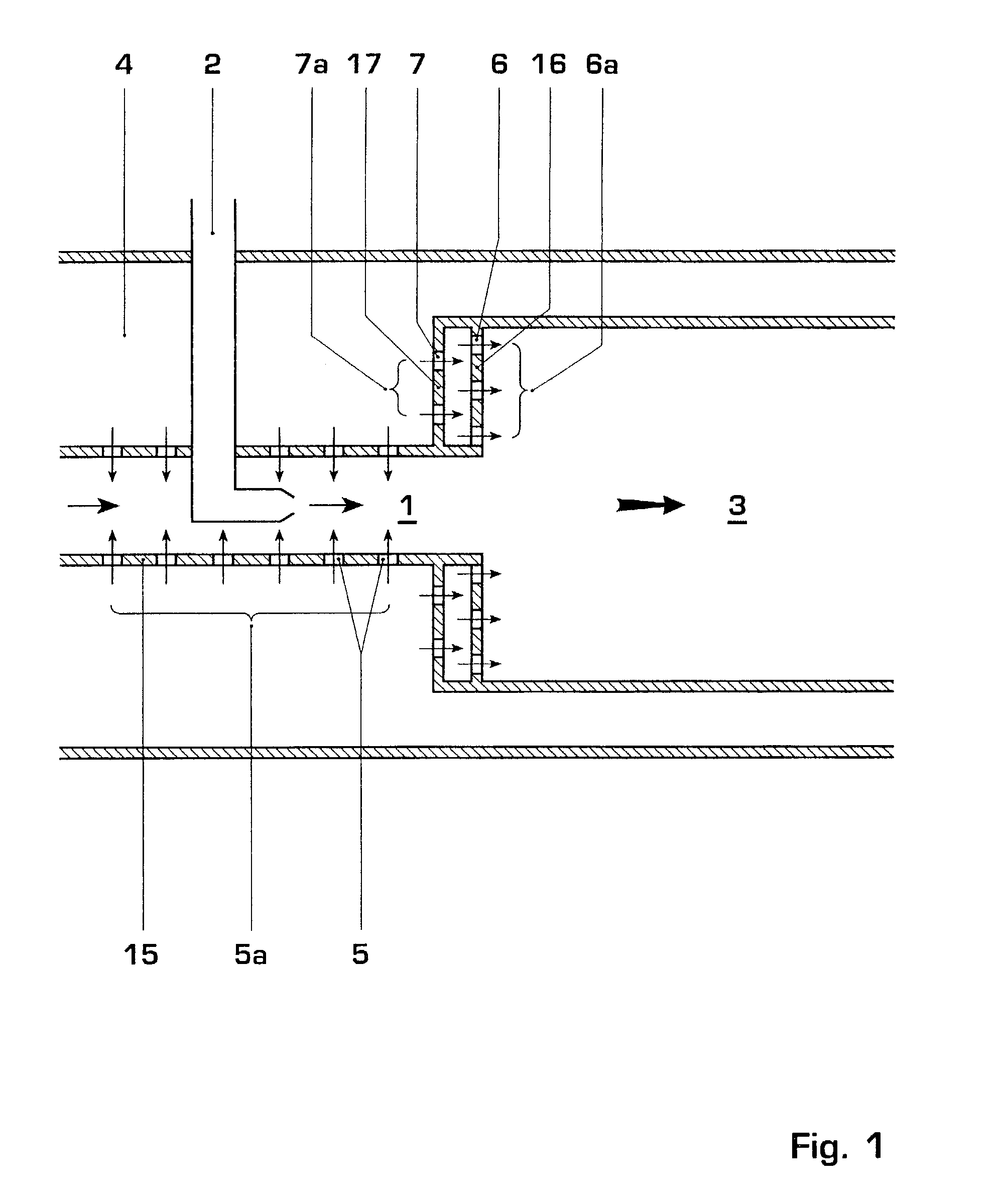
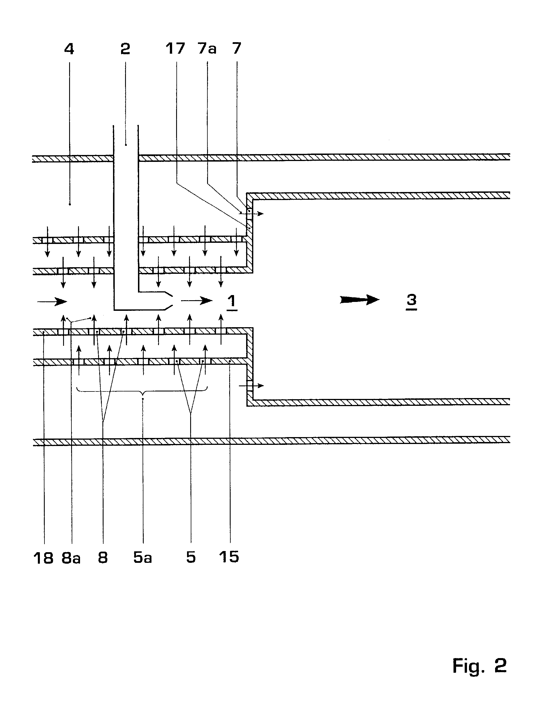
[0038]The figures are schematic and only the elements essential for the understanding of the invention are shown. In particular, the figures do not show the high and low pressure turbines (located upstream of burner and downstream of the combustion chamber, respectively), the primary combustion system or the compressor. These components would be well-understood to the skilled addressee and may be conventional.

[0039]FIG. 1 shows a burner 1, which is fed with a pre-mixed stream of reactants obtained by mixing the hot oxygen stream (i.e. the products of the primary combustion) entering the burner 1 with fuel injected by lance 2.

[0040]The mixture enters the combustion chamber 3, where combustion occurs. The walls of the burner 1 are perforated and are cooled by air flowing from the plenum 4. In this regard, the burner mixing tube 15 comprises rows of perforations 5, which admit air flows 5a. These serve to cool the mixing tube 15 by means of effusion. The axially facing front panel 17 o...


PUM


Abstract

A reheat combustion system for a gas turbine comprises a mixing tube adapted to be fed by products of a primary combustion zone of the gas turbine and by fuel injected by a lance; a combustion chamber fed by the said mixing tube; and at least one perforated acoustic screen. The or each said acoustic screen is provided inside the mixing tube or the combustion chamber, at a position where it faces, but is spaced from, a perforated wall thereof. In use, the perforated wall experiences impingement cooling as it admits air into the combustion system for onward passage through the perforations of the said acoustic screen, and the acoustic screen damps acoustic pulsations in the mixing tube and combustion chamber.

Description

BACKGROUND OF THE INVENTION[0001]1. Field of the Invention[0002]This invention relates to a reheat combustion system for a gas turbine. In particular, the invention relates to such a system comprising acoustic damping.[0003]In modern industrial gas turbines operating with pre-mix combustion flames, it is important to suppress pressure pulsations in order to maintain the quality of the combustion process and preserve structural integrity of the turbine. To date, acoustic damping techniques have been employed in order to dissipate acoustic power and thereby reduce the pressure pulsations.[0004]2. Brief Description of Related Art[0005]In conventional gas turbines (having only one combustion zone) it is known to damp low frequency pulsations using Helmholtz resonators. The simplest design for a Helmholtz resonator comprises a cavity, with a neck through which the fluid inside the resonator communicates with an enclosure that the resonator is applied to. At its resonance frequency, the H...

Claims


Application Information

Patent Timeline
Patent Type & Authority Patents(United States)
IPC IPC(8): F02C1/06F02C6/00F23D11/40F23M20/00F23R3/28
CPCF23D11/402F23R3/286F23M20/005F23R2900/03341F23R2900/00014
Inventor BELLUCCI, VALTERFLOHR, PETERPASCHEREIT, CHRISTIAN OLIVERSCHUERMANS, BRUNOTABACCO, DANIELE
Owner ANSALDO ENERGIA IP UK LTD
Why Eureka
Try Eureka