Eureka AIR delivers breakthrough ideas for toughest innovation challenges, trusted by R&D personnel around the world.

Method and apparatus to measure gas amounts adsorbed on a powder sample

Inactive Publication Date: 2006-01-03
TSINGHUA UNIV
View PDF3 Cites 29 Cited by
  • Summary
  • Abstract
  • Description
  • Claims
  • Application Information

AI Technical Summary

Benefits of technology

[0072]The invention gives experimental results with higher accuracy due to the use of a supply chamber with a gas amount to supply gas such that the pressure in the sample cell can reach the pressure required at the end of the adsorption experiment without a need to refill the supply chamber. This is different from the prior art where the supply chamber is small and it experiences significant pressure drop after supplying some gas, which leads to a need for the supply chamber to be refilled with gas many times during a measurement, resulting in its accuracy being poorer due to the cumulative error from the addition of the errors made at each refill.
[0073]Due to that there is no need for multiple refilling of the supply chamber, it is easy to automate the measurements.

Problems solved by technology

This embodiment has the disadvantage that the chamber has to be refilled or evacuated for each data point measurement.
This embodiment has the disadvantage that the dosing manifold has to be refilled a number of times in the course of measuring the isotherms and the dosing volume has to be refilled for each data point measurement.
Additional disadvantages in these apparatuses are that the resolution and accuracy of the isotherm measurements are low.
Due to this small size, the absence of an effective pressure control device in the device and intermittent dosing in discrete units, there are large changes in the pressure in the sample cell with each dose which result in a low resolution of the isotherm, that is, the points of the isotherm are spaced far apart.
This increases the experimental error since as each refill or evacuation gives rise to an experimental error, the errors are proportional to the number of refills.
One disadvantage in using this method is that the change in pressure in the supply chamber is very small relative to its magnitude, and due to the limited precision of pressure measuring devices, this limits the number of measured points in the isotherm, that is, there is limited resolution.
Another disadvantage is again due to the change in pressure in the supply chamber being small relative to its magnitude.
Due to the resulting limited precision in calculating the pressure change, this limits the volumetric size of the supply chamber to a small size which has to be small enough to give detectable changes in its pressure with the flow out of it of very small quantities of gas.
A small size for the supply chamber has the disadvantage that, as gas is dosed from it, its pressure quickly falls and the supply chamber has to be refilled with gas to a higher pressure many times in the course of measuring an isotherm.
The accuracy is limited since the error is proportional to the number of refills because of errors made at each refill.
Automation is more complicated because there is also the need to automate the refilling of the supply chamber.
The disadvantages in the method of Borghard et al. are the same as discussed above, namely, a requirement to keep the flow rate very slow means that the change in pressure in the supply chamber is very small, and due to the limited precision of pressure measuring devices, this limits the number of measured points of the uptake curve, that is, there is limited resolution.
Another disadvantage is that the limited precision of the pressure measuring devices limits the volumetric size of the supply chamber to a small size and there is then only a limited pressure range over which uptake curves can be measured.
The disadvantage of this method is that its construction and operation is quite difficult and expensive because the reference subsystem should precisely match the sample subsystem.

Method used


Image

  • Method and apparatus to measure gas amounts adsorbed on a powder sample
  • Method and apparatus to measure gas amounts adsorbed on a powder sample
  • Method and apparatus to measure gas amounts adsorbed on a powder sample

Examples


example

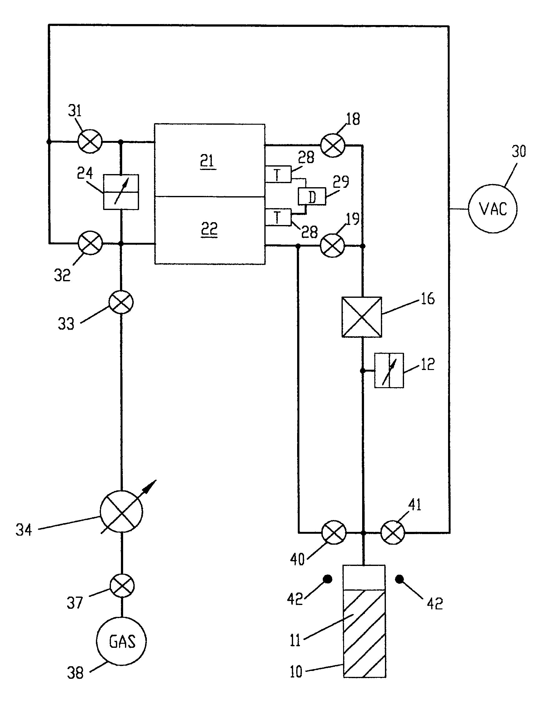
[0093]An example of a nitrogen adsorption and desorption experiment follows. The free space in sample cell 10 which is the volume of sample cell 10 not occupied by sample 11, is first determined. Then, the adsorption isotherm and the desorption isotherm are measured. In the following, the volume of supply chamber 21 includes the volume of conduits to gas flow control means 16, and the volume of free space in sample cell 10 includes the volume of conduits to gas flow control means 16. The volume of supply chamber 21 is already precisely predetermined from previous measurements.

1. Measurement and Calculation of the Free Space in Sample Cell 10.

[0094]The free space in sample cell 10 is determined by gas law relationships using a three step procedure. In the first step, the free space at ambient temperature of sample cell 10 without any sample is measured. Empty sample cell 10 is isolated from supply chamber 21 and reference chamber 22 and sample cell 10 is evacuated. Supply chamber 21 ...


PUM


Abstract

A method and apparatus for measuring the gas amounts adsorbed on a powder which directly measures pressure changes in a gas supply chamber with the use of differential pressure sensors between the gas supply chamber and a reference chamber which gas amount is maintained constant. Calculations of the gas amounts adsorbed are based on the pressure changes in a sample cell and the pressure changes in the gas supply chamber or a gas reference chamber. The method and apparatus of this invention measures the adsorption or desorption isotherm or gas uptake at constant pressure curve of a powder with, as compared with presently available measurement techniques, increased accuracy and resolution. The experimental data can be analyzed to obtain information on the surface area, pore size distribution, pore volume, pore structure and diffusion coefficient of the powder.

Description

CROSS-REFERENCE TO RELATED APPLICATIONS[0001]Priority is claimed pursuant to 35USC119a,b from People's Republic of China patent application number 03100285.4, filed on Jan. 10, 2003 and continuation-in-part application number 200310113533.2, filed on Nov. 14, 2003.STATEMENT REGARDING FEDERALLY SPONSORED RESEARCH OR DEVELOPMENT[0002]Not applicable.REFERENCE TO A MICROFICHE APPENDIX[0003]Not applicable.BACKGROUND OF THE INVENTION[0004]Herein, the term “adsorptive” is used to refer to a gas used which is adsorbed, the terms “adsorption isotherm” and “desorption isotherm” refer to data measured and plotted as curves of adsorbed amount versus pressure at a constant temperature onto a powder using physically adsorbed adsorptives, and the term “chemisorption isotherm” refers to similar curves of data measured and plotted but using chemically and selectively adsorbed adsorptives. This invention is related to the practice of measuring adsorption isotherms and desorption isotherms of solid po...

Claims


Application Information

Patent Timeline
IPC IPC(8): G01N15/08G01N7/04
CPCG01N7/04G01N2015/0866G01N15/0893
Inventor WANG, DEZHENGWEI, FEIWANG, JINFU
Owner TSINGHUA UNIV
Why Eureka
Eureka Blog
Learn More