
Battery state estimation control logic and architectures for electric storage systems

Active Publication Date: 2019-05-02
GM GLOBAL TECH OPERATIONS LLC
View PDF0 Cites 10 Cited by
  • Summary
  • Abstract
  • Description
  • Claims
  • Application Information

AI Technical Summary

Benefits of technology

The patent text describes a battery management system for electric vehicles that uses a reference electrode to estimate the state of the battery cells. This helps to eliminate uncertainty caused by hysteresis in the battery cells, which can cause problems in estimating the battery's state of charge and power. The system is designed to enhance the fast-charge capability of the vehicle and improve its overall fuel economy. The battery cells used in the system have a cathode half-cell that contains a reference electrode and a thin layer of material that helps to restore voltage-based battery state estimation. This design is compatible with existing battery cell production methods and does not require additional tooling or costly equipment modifications. Overall, the technical effect of the patent text is to provide a more accurate and reliable estimation of the battery's state of charge and power, which can improve the performance and reliability of electric vehicles.

Problems solved by technology

Consequently, measured and calculated open circuit voltage will not provide battery state of charge estimation.
Battery cells with anodes that contain silicon may exhibit significant hysteresis in the open circuit voltage (OCV), which may introduce a large uncertainty in the relationship between full-cell voltage signal and the battery's state of charge (SOC) and state of power (SOP).

Method used


Image

  • Battery state estimation control logic and architectures for electric storage systems
  • Battery state estimation control logic and architectures for electric storage systems
  • Battery state estimation control logic and architectures for electric storage systems

Examples


Embodiment Construction

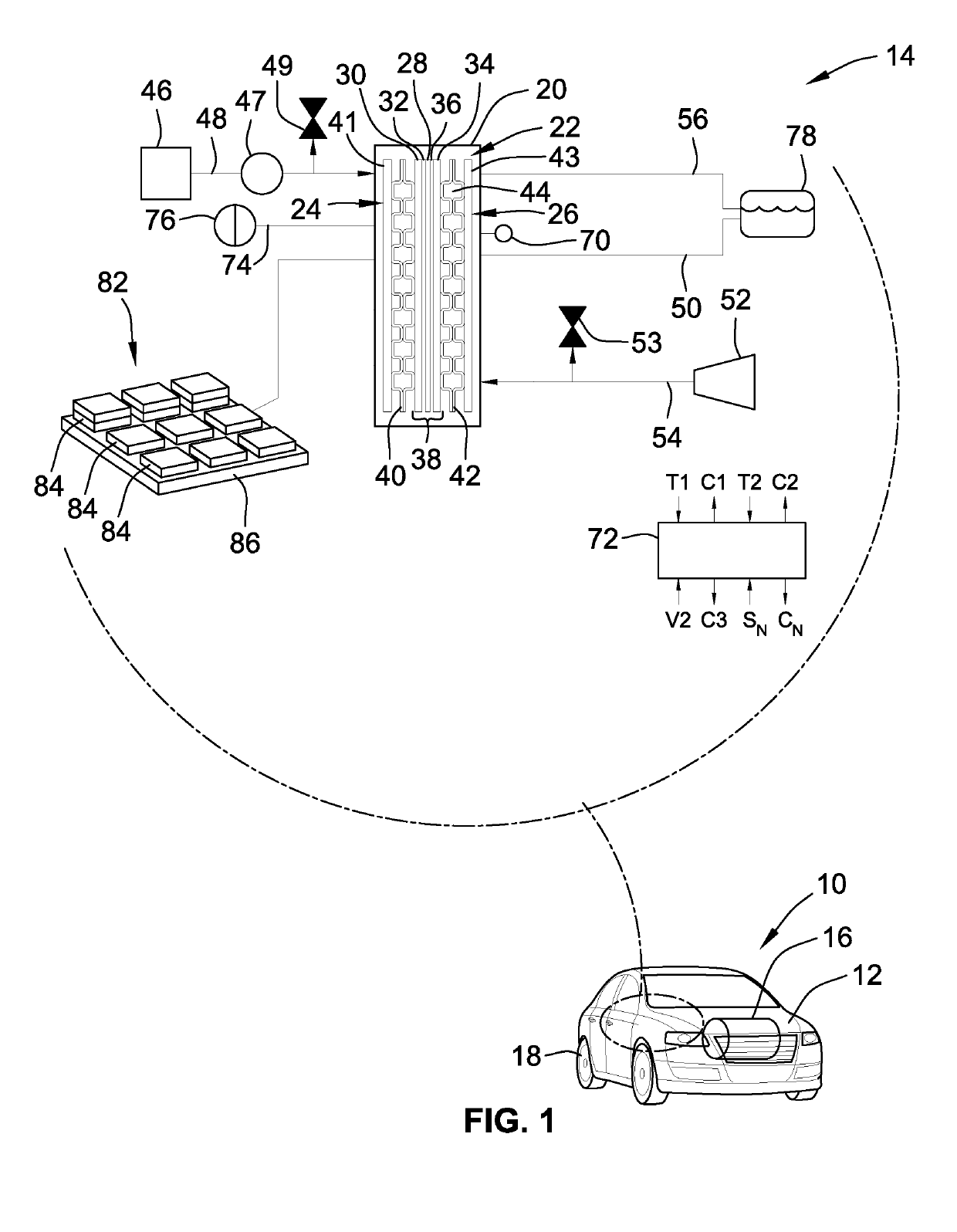
[0018]This disclosure is susceptible of embodiment in many different forms. There are shown in the drawings and will herein be described in detail representative embodiments of the disclosure with the understanding that these illustrated examples are provided as an exemplification of the disclosed principles, not limitations of the broad aspects of the disclosure. To that extent, elements and limitations that are described, for example, in the Abstract, Summary, and Detailed Description sections, but not explicitly set forth in the claims, should not be incorporated into the claims, singly or collectively, by implication, inference or otherwise.

[0019]For purposes of the present detailed description, unless specifically disclaimed: the singular includes the plural and vice versa; the words “and” and “or” shall be both conjunctive and disjunctive; the word “all” means “any and all”; the word “any” means “any and all”; and the words “including” and “comprising” and “having” mean “inclu...


PUM


Abstract

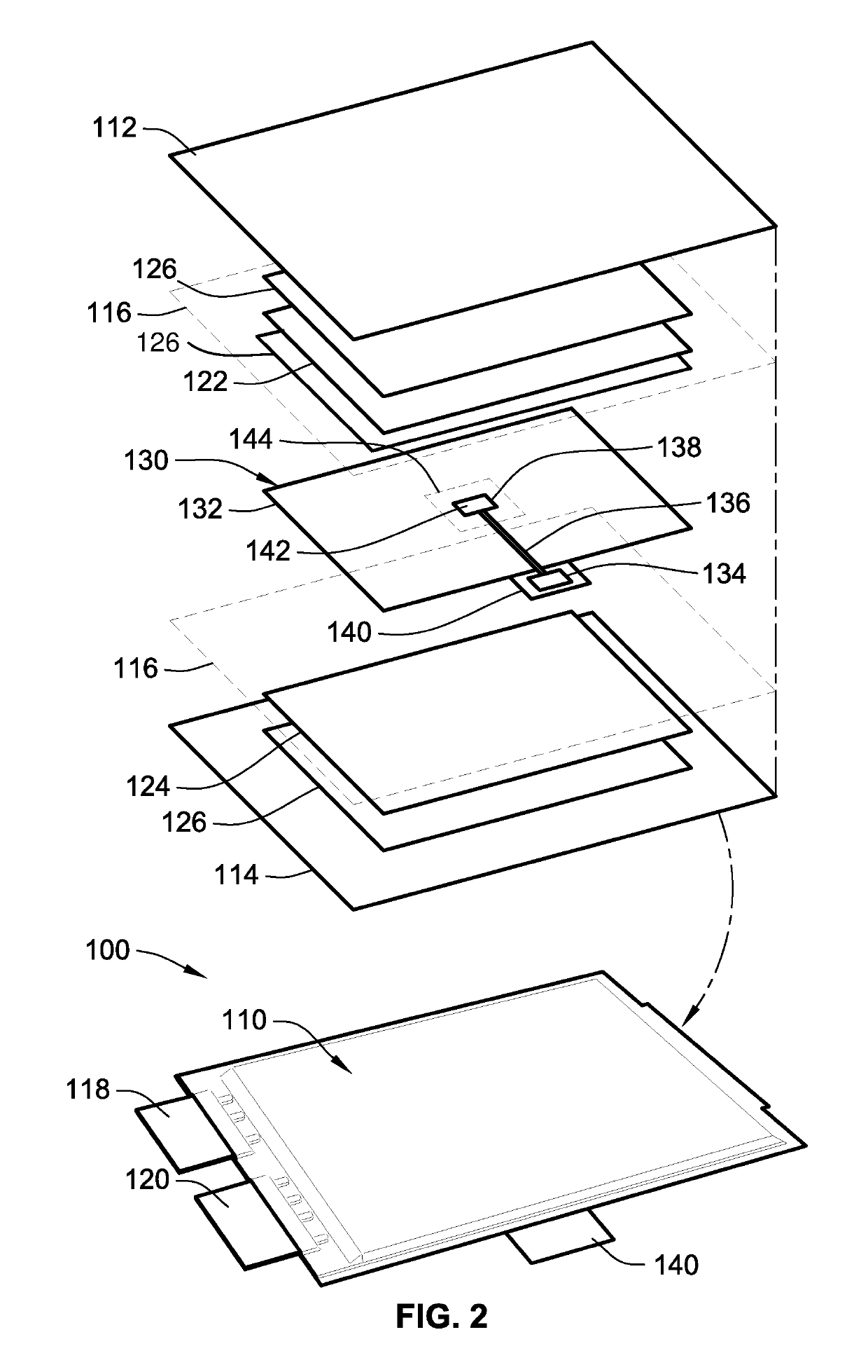
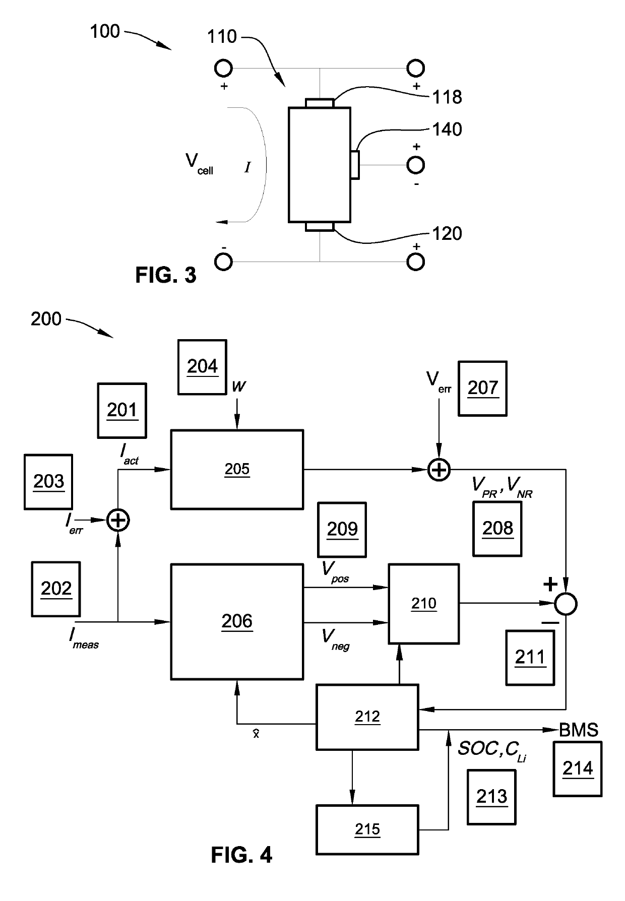
Disclosed are battery management systems with control logic for battery state estimation (BSE), methods for making / using / assembling a battery cell with a reference electrode, and electric drive vehicles equipped with a traction battery pack and BSE capabilities. In an example, a battery cell assembly includes a battery housing with an electrolyte composition stored within the battery housing. The electrolyte composition transports ions between working electrodes. A first working (anode) electrode is attached to the battery housing in electrochemical contact with the electrolyte composition. Likewise, a second working (cathode) electrode is attached to the battery housing in electrochemical contact with the electrolyte composition. A reference electrode is interposed between the first and second working electrodes, placed in electrochemical contact with the electrolyte composition. The reference electrode and one or both working electrodes cooperate to output a half-cell voltage signal that is indicative of a battery state of the battery cell assembly.

Description

INTRODUCTION[0001]The present disclosure relates generally to electric storage systems employing rechargeable batteries. More specifically, aspects of this disclosure relate to systems, methods, and devices for estimating battery state, such as state of charge (SOC) or state of power (SOP), in electric drive vehicles.[0002]Current production motor vehicles, such as the modern-day automobile, are originally equipped with a powertrain that operates to propel the vehicle and power the onboard vehicle electronics. In automotive applications, for example, the vehicle powertrain is generally comprised of a prime mover that delivers driving power through a multi-speed power transmission to the vehicle's final drive system (e.g., differential, axle, and road wheels). Automobiles have generally been powered by a reciprocating-piston type internal combustion engine (ICE) because of its ready availability and relatively inexpensive cost, light weight, and overall efficiency. Such engines inclu...

Claims


Application Information

Patent Timeline
IPC IPC(8): B60L11/18H01M10/42H01M2/10H01M10/44H01M10/48H01M4/13B60L50/64
CPCB60L11/1861H01M10/425H01M2/1077H01M10/44H01M10/48H01M4/13H01M10/0445H01M2220/20H01M16/006H01M10/0413H01M10/049H01M4/5825H01M4/136Y02T10/7072Y02T10/70Y02T90/12Y02E60/50Y02E60/10Y02P70/50H01M50/249B60L50/64H01M50/211H02J7/00B60L58/12
Inventor KOCH, BRIAN J.WAMPLER, CHARLES W.VERBRUGGE, MARK W.BAKER, DANIEL R.
Owner GM GLOBAL TECH OPERATIONS LLC
Learn More