
Biosensor

a biosensor and sensor technology, applied in the field of biosensors, can solve the problems of inability to absorb water, inability to detect biosensors, and inability to detect biosensors, and achieve the effect of high water absorption

Inactive Publication Date: 2006-01-03
ARKRAY INC
View PDF24 Cites 149 Cited by
  • Summary
  • Abstract
  • Description
  • Claims
  • Application Information

AI Technical Summary

Benefits of technology

The present invention provides a biosensor that can measure an analyte in a sample with high precision without being affected by impurities in the sample or humidity. The biosensor includes a substrate, a reagent layer containing a reagent, and an electrode system. The reagent layer contains particules that prevent impurities from attaching to the electrodes. The biosensor is not susceptible to the influence of humidity and can measure the analyte with high precision regardless of the properties of the sample. The average particle diameter of the particules is preferably in the range from 0.1 to 45 μm, and more preferably in the range from 0.5 to 30 μm. The biosensor is not limited to a specific number of particules, but preferably has a particle size distribution in the range from 0.01 to 100 μm. The particules are preferably formed of a polymer compound that does not contain an impurity causing electrolysis and is electrochemically inactive. The biosensor can measure the analyte with high precision even in samples with high impurity content.

Problems solved by technology

However, the method employing the anion filter has a problem in that, although the anion filter is effective in suppressing the solid components from passing therethrough, it has no effect on the soluble components, such as protein, in the sample, for example.
Furthermore, in the methods other than this method, since the water-soluble polymer and the like are used, the water absorptivity is high so that the biosensor is susceptible to humidity, which causes a problem in that the enzyme reaction is slow, for example.
However, it is considered that this is caused by the physical adsorption or the like of the impurities to the particulates.

Method used


Image

  • Biosensor
  • Biosensor
  • Biosensor

Examples


embodiment 1

(Embodiment 1)

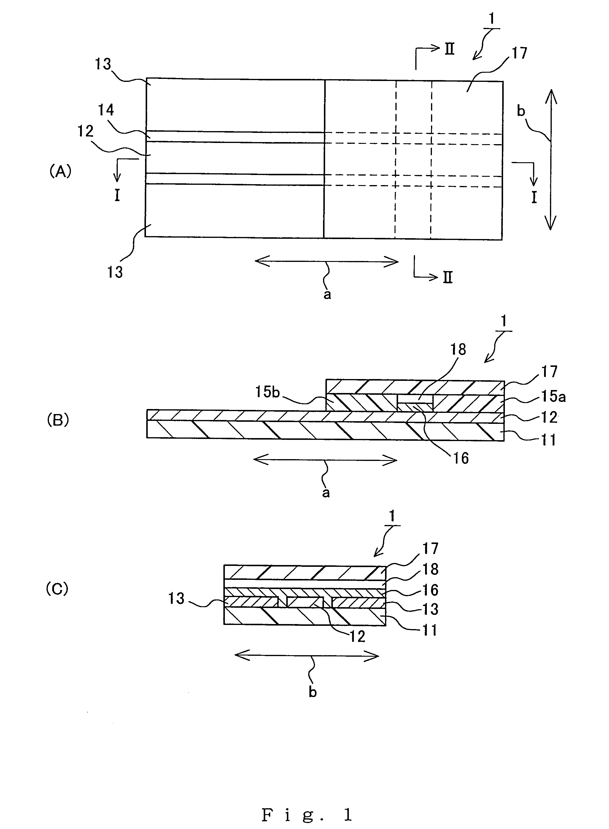
[0039]FIGS. 1A–1C show an example of a biosensor of the present invention. FIG. 1A is a plan view of the biosensor, FIG. 1B is a cross-sectional view taken along the line I—I of FIG. 1A, and FIG. 1C is a cross-sectional view taken along the line II—II of FIG. 1A. As shown in the drawings, in this biosensor 1, an electrode system including a working electrode 12 and counter electrodes 13 is disposed on a substrate 11. A reagent layer 16, which is a single layer containing a reagent and particulates, is formed on one end portion (on the right side of FIG. 1A, and at the upper right of FIG. 1B) of the electrode system. The two counter electrodes 13 are disposed on the opposite ends in the width direction (the direction indicated by the arrow “b”) of the substrate 11, and the working electrode 12 is disposed in the center in the width direction of the substrate 11. These electrodes 12 and 13 extend in the longitudinal direction (the direction indicated by the arrow “a”) of...

embodiment 2

(Embodiment 2)

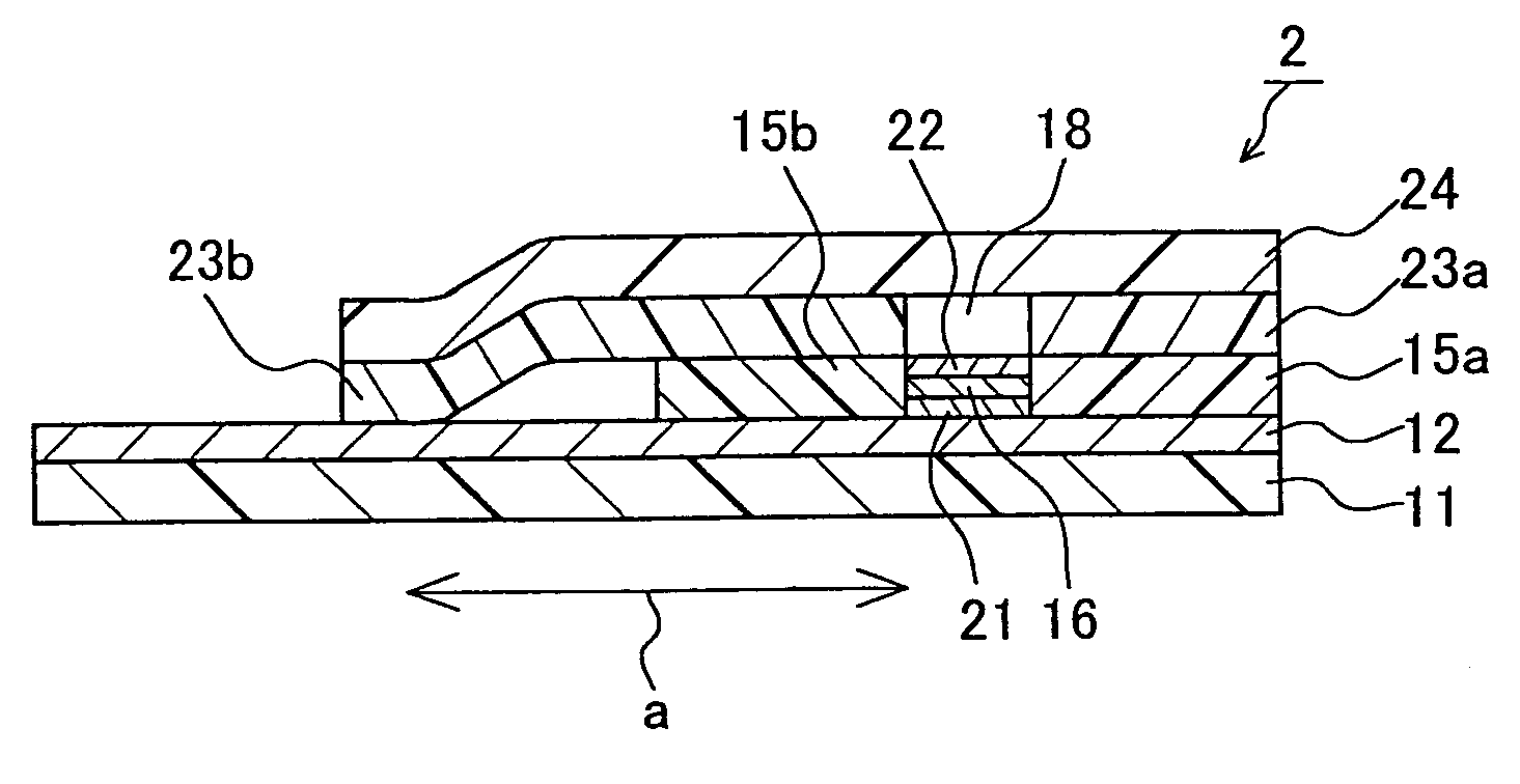
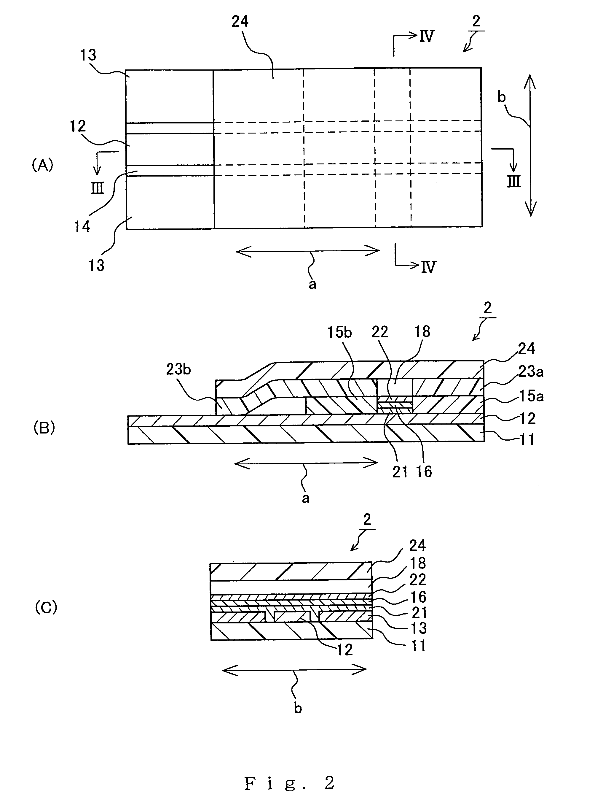
[0069]FIGS. 2A–2C show another example of a biosensor of the present invention. FIG. 2A is a plan view of the biosensor, FIG. 2B is a cross-sectional view taken along the line III—III of FIG. 2A, and FIG. 2C is a cross-sectional view taken along the line IV—IV of FIG. 2A. In FIGS. 2A–2C, the same components as those in FIGS. 1A–1C bear the same reference numeral.

[0070]As shown in the drawings, in this biosensor 2, an electrode system including a working electrode 12 and counter electrodes 13 is disposed on a substrate 11. A laminate, in which an inorganic gel-containing layer 21, a reagent layer 16, and a surfactant-containing layer 22 are laminated in this order, is formed on one end portion (at the upper right of FIGS. 2A and 2B) of the electrode system. The reagent layer 16 contains a reagent and particulates. The two counter electrodes 13 are disposed on the opposite ends in the width direction (the direction indicated by the arrow “b”) of the substrate 11, and the...

embodiment 3

(Embodiment 3)

[0077]This embodiment is an example of the biosensor of the present invention in which a reagent layer is a laminate including a reagent-containing layer and a particulate-containing layer. FIG. 3 is a cross-sectional view of this biosensor. In FIG. 3, the same components as those in FIGS. 1A–1C bear the same reference numeral.

[0078]As shown in FIG. 3, the biosensor 3 has the same configuration as in Embodiment 1, except that a particulate-containing layer 32 is laminated on the substrate 11, on which the electrodes have been disposed, via a reagent-containing layer 31. The reagent-containing layer 31 and the particulate-containing layer 32 can be formed in the following manner, for example. First, a solution containing a reagent and a solution containing particulates are prepared. The solution containing the reagent is poured into the space between the spacers and dried, and thereafter, the solution containing the particulates is poured thereon and dried.

[0079]In this...


PUM

PropertyMeasurementUnit
particle diameteraaaaaaaaaa
particle size distributionaaaaaaaaaa
particle diameteraaaaaaaaaa

Abstract

A biosensor is provided, which can measure an analyte in a sample with high precision. The biosensor is produced by disposing a electrode system including a working electrode 12 and a counter electrode 13 on a substrate 11, and then forming a reagent layer 16 containing a reagent and particulates on the electrode system. The influence of the impurities in the sample on the electrode system can be eliminated by the particulates. The average particle diameter of the particulates preferably is in the range from 0.1 to 45 μm.

Description

CROSS REFERENCE TO RELATED APPLICATIONS[0001]This application is a 35 U.S.C. 371 of PCT application PCT / JP01 / 09367 filed on Oct. 25, 2001.TECHNICAL FIELD[0002]The present invention relates to a biosensor.BACKGROUND ART[0003]Biosensors that can quantify a specific analyte in a sample simply and rapidly, for example, without dilution or stirring of the sample have been used widely. In general, such a biosensor can be produced by forming an electrode system having a working electrode (also referred to as “measuring electrode”) and a counter electrode on an electrically insulating substrate by a method such as screen printing, and then forming a reactive layer including a redox enzyme that reacts with the analyte and an electron-accepting substance on the electrode system, as disclosed in Japanese Patent No. 2517153, for example. When the reactive layer is in contact with the sample containing the analyte, the analyte is oxidized by the catalytic action of the redox enzyme, and the elec...

Claims


Application Information

Patent Timeline
Patent Type & Authority Patents(United States)
IPC IPC(8): G01N27/327C12Q1/00
CPCC12Q1/002C12Q1/001
Inventor YAGI, YUJI
Owner ARKRAY INC
Learn More