Mask for reducing proximity effect

a mask and proximity effect technology, applied in the field of masks for reducing proximity effects, can solve the problems of lithographic process, limit resolution r cannot be reduced by only enlarging, and mask error enhancement factor (meef) is too large, so as to improve image contrast and mask error enhancement factor (meef), the depth of focus is further improved, and the resolution is extended.

Inactive Publication Date: 2006-01-03
MACRONIX INT CO LTD
View PDF5 Cites 10 Cited by
  • Summary
  • Abstract
  • Description
  • Claims
  • Application Information

AI Technical Summary

Benefits of technology

[0017]The objective of the present invention is to provide a mask with a plurality of ladder-shaped assist features for reducing proximity effect. This invention will make the iso trench pattern become line-space dense like pattern. Not only the process window, but also the image contrast will improve.
[0019]Compared with the prior art, the depth-of-focus is further improved, the process window is wider and the resolution is extended according to the present invention. This present invention also improves the image contrast and mask error enhancement factor (MEEF), thus the resolution and critical dimension uniformity is also improved. Additionally, the location and number of the ladder-shaped assist feature are easy friendly to design, and therefore the present invention is adaptable to the present lithographic system without changing the process and increasing the production cost.

Problems solved by technology

Due to serious impact to process window, the limit resolution R cannot be reduced by only enlarging NA.
As the size of the critical dimension shrinks rapidly, the prior art cannot meet the future requirement and possesses the following disadvantages:1. Without the assist feature design, the process window of the lithographic process cannot meet the product criteria (especially for iso trench or iso line pattern) and the mask error enhancement factor (MEEF) will be too large.2. With assist feature design such as the technique disclosed in U.S. Pat. No. 5,242,770, the process window may not be enough for product criteria for an even smaller isolation trench design rule.
Besides, the location and the number of the assist features are not easy for design.

Method used


Image

  • Mask for reducing proximity effect
  • Mask for reducing proximity effect
  • Mask for reducing proximity effect

Examples


first embodiment

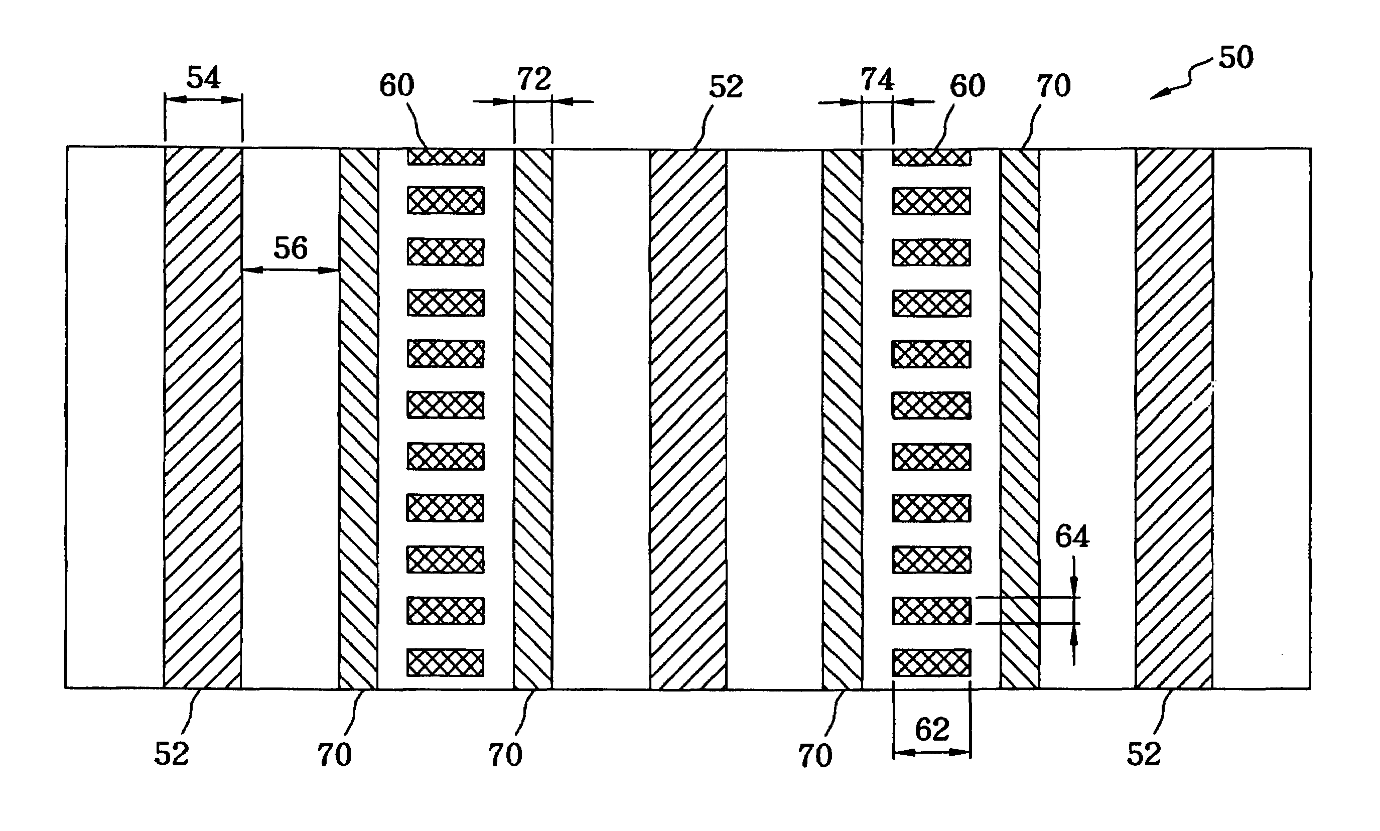
[0030]FIG. 3(a) is a close-up diagram for the mask 50 for forming 0.12-micrometer isolation trenches according to the present invention. The pattern of the mask 50 comprises a plurality of line-shaped features 52, a plurality of groups of first assist features 60 (each group of first assist features 60 positioned between two adjacent line-shaped features 52), and a plurality of second assist features 70 positioned between the line-shaped features 52 and the groups of first assist features 60. Each of the line-shaped features 52 corresponds to one isolation trench to be formed on the silicon wafer 44. The first assist feature 60 is approximately rectangular in shape and the width 62 at the direction perpendicular to the line-shaped feature 52 is larger than the length 64 at the direction parallel to the line-shaped feature 52. Since the first assist feature 60 is arranged in perpendicular to the line-shaped feature 52 and looks like a ladder, it is named a ladder-shaped assist featur...

second embodiment

[0037]FIG. 8 is a close-up diagram of the mask 50 for forming the 0.12-micrometer isolation trench according to the present invention. The pattern of the mask 50 comprises a plurality of line-shaped features 52 and a plurality of groups of third assist features 90, wherein each group of third assist features is positioned between two adjacent line-shaped features 52. In order to keep the third assist feature 90 non-resolvable, the space 92 between the line-shaped feature 52 and the group of the third assist feature 90 is larger than the width 54 of the line-shaped feature 52. The length 94 of the third assist feature 90 is preferably smaller than two-fifths of the wavelength but larger than one-fourth of the wavelength of an exposure source. The space 96 between two adjacent third assist features 90 is larger than the length 94 of the third assist feature 90. The third assist feature 90 can be approximately rectangular in shape and the width 98 at the direction perpendicular to the ...


PUM

PropertyMeasurementUnit
widthaaaaaaaaaa
wavelengthaaaaaaaaaa

Abstract

The present invention discloses a mask for reducing the proximity effect. The mask comprises a plurality of line-shaped features, a plurality of first assist features positioned between the line-shaped features and a plurality of second assist features positioned between the line-shaped feature and the first assist feature. The line-shaped feature corresponds to isolation trenches to be formed on a silicon wafer. The first assist feature is rectangular in shape and has a larger width at the direction perpendicular to the line-shaped features. The width of the second assist feature is smaller than two-fifths of the wavelength but larger than one-fourth of the wavelength of an exposure source. The size of the first assist feature and the second assist feature is so designed to be non-resolvable, while the line-shaped feature is resolvable and transferred to the silicon wafer.

Description

BACKGROUND OF THE INVENTION[0001]1. Field of the Invention[0002]The present invention relates to a mask for reducing proximity effect, and more particularly, to a mask with a plurality of ladder-shaped assist features for reducing proximity effect. Those ladder-shaped assist features will make the iso space patterns become more line-space patterns like. Not only the process window, but also the image contrast will improve.[0003]2. Description of Related Art[0004]Conventional processes for the fabrication of semiconductor wafers often incorporate a lithographic process to create a desired pattern on a silicon wafer. In the photolithography technology, a limitation R for representing a dimension of a minimum pattern is represented by the Rayleigh formula:R=k1λ / NAWhere the k1 is a constant depending upon the photolithography process;[0005]λ is a wavelength of an exposure light; and[0006]NA is a numeral aperture of an exposure system.[0007]Therefore, the higher NA, the better R.[0008]On...

Claims


Application Information

Patent Timeline
Patent Type & Authority Patents(United States)
IPC IPC(8): G06F17/50G03C5/00G03F1/14G03F9/00
CPCG03F1/36G03F1/144
Inventor YANG, CHIN CHENG
Owner MACRONIX INT CO LTD
Why Eureka
Try Eureka