
Door mirror

a technology for door mirrors and mirrors, applied in mirrors, instruments, mountings, etc., can solve the problems of difficult to view the rear wheel portion, difficult to make sure of the safety behind the vehicle's body, and difficult to make sure of the safety around the rear wheels, etc., and achieve the effect of high adaptability

Inactive Publication Date: 2006-01-10
ATORASU OOTO
View PDF19 Cites 6 Cited by
  • Summary
  • Abstract
  • Description
  • Claims
  • Application Information

AI Technical Summary

Benefits of technology

"The invention is a door mirror for vehicles that can eliminate blind spots and allow drivers to easily see what is behind their vehicle's body. The mirror is installed on the outside of the door and has a divided surface that can adjust the reflection angle independently. This allows the driver to see the image they need to observe while driving in reverse. The mirror can be adjusted to face outward, providing a wider view. The mirror can also be supported by a common base that allows for variable angles, making it highly adaptable. Overall, this invention improves safety and visibility for drivers."

Problems solved by technology

When altering the reflection angle of the mirror so as to make such blind spot visible, an antinomic problem occurs of permitting a spot having been visible to become a blind spot.
In addition, there has occurred another problem that when adjusting the reflection angle of the mirror so as to make visible what is in the distance behind the vehicle's body, it becomes difficult to view the rear wheel portion so as to prevent the vehicle from running onto the shoulder of a road due to the difference in distance from the shoulder between the front wheel and the rear wheel.
Further, when two vehicles pass each other on a narrow road or when a vehicle is put in a small garage, the door mirror is often folded so as to make the vehicle's width as small as possible; however, this also causes a problem in that once the door mirror is folded, what is behind the vehicle's body, that has been seen in the mirror until then, becomes completely invisible, making it difficult to make sure of the safety behind the vehicle's body.
Still further, when adjusting the reflection angle of the mirror so as to make visible what is in the distance behind the vehicle's body, as described above, it also becomes difficult to make sure of the safety around the rear wheels, causing a problem of permitting accidents, such as wheels' coming off, to be more likely to occur.
However, in the former invention, that is, the door mirror of which mirror surface has its outer portion convexly curved to broaden the driver's view, since the flat mirror surface, as a main portion, and the convexly curved mirror surface are continuously formed, the images reflected in the door mirror seem to the driver to change from a natural state at the main portion to a distorted state at the outer portion, which causes a problem of making the images less readable, and moreover, a problem of the driver's getting confused by the distortedly changing images and being unable to look carefully frontward.
Further, even with such a door mirror, the problem cannot be overcome of making invisible what is in the distance behind the vehicle's body when adjusting the reflection angle of the door mirror to make the rear wheels and their vicinities visible with an intention of preventing the rear wheels from running onto the shoulder of a road.
In the latter invention, that is, the door mirror of which side surface has another smaller mirror affixed thereon, when using the door mirror in the unfolded state, the smaller mirror affixed on its side surface is not only useless for making sure of the safety behind the vehicle's body, but liable to be an obstacle of other drivers' safe driving because it reflects in an unexpected direction the sunlight or headlamp lights of oncoming cars.
Further, such a door mirror has another problem of being more likely to come in contact with some other things during the vehicle's moving, and once having come in contact with others, it is easily broken, as a result, it will never be able to be utilized again.

Method used


Image

  • Door mirror
  • Door mirror
  • Door mirror

Examples


embodiment 1

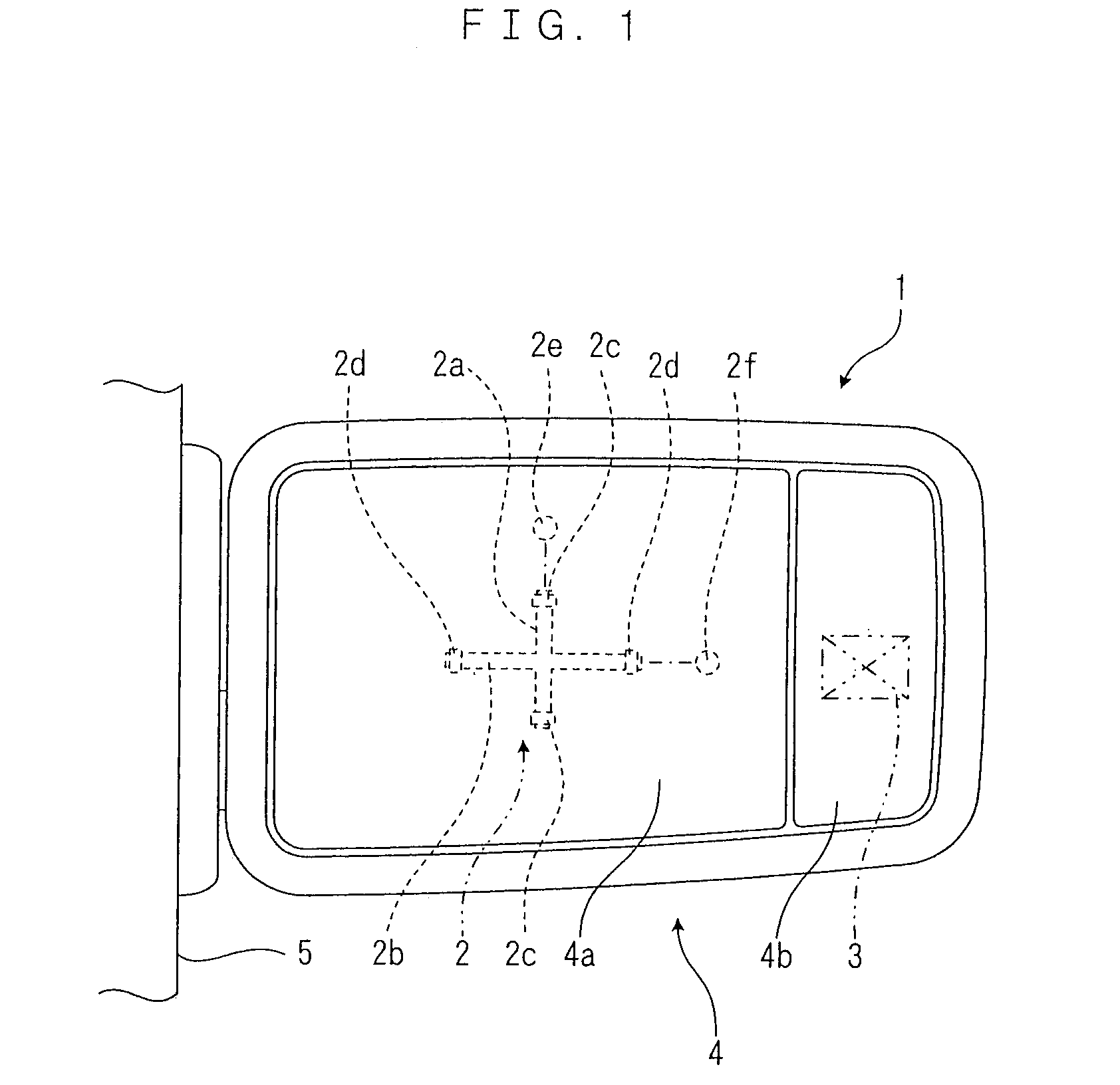
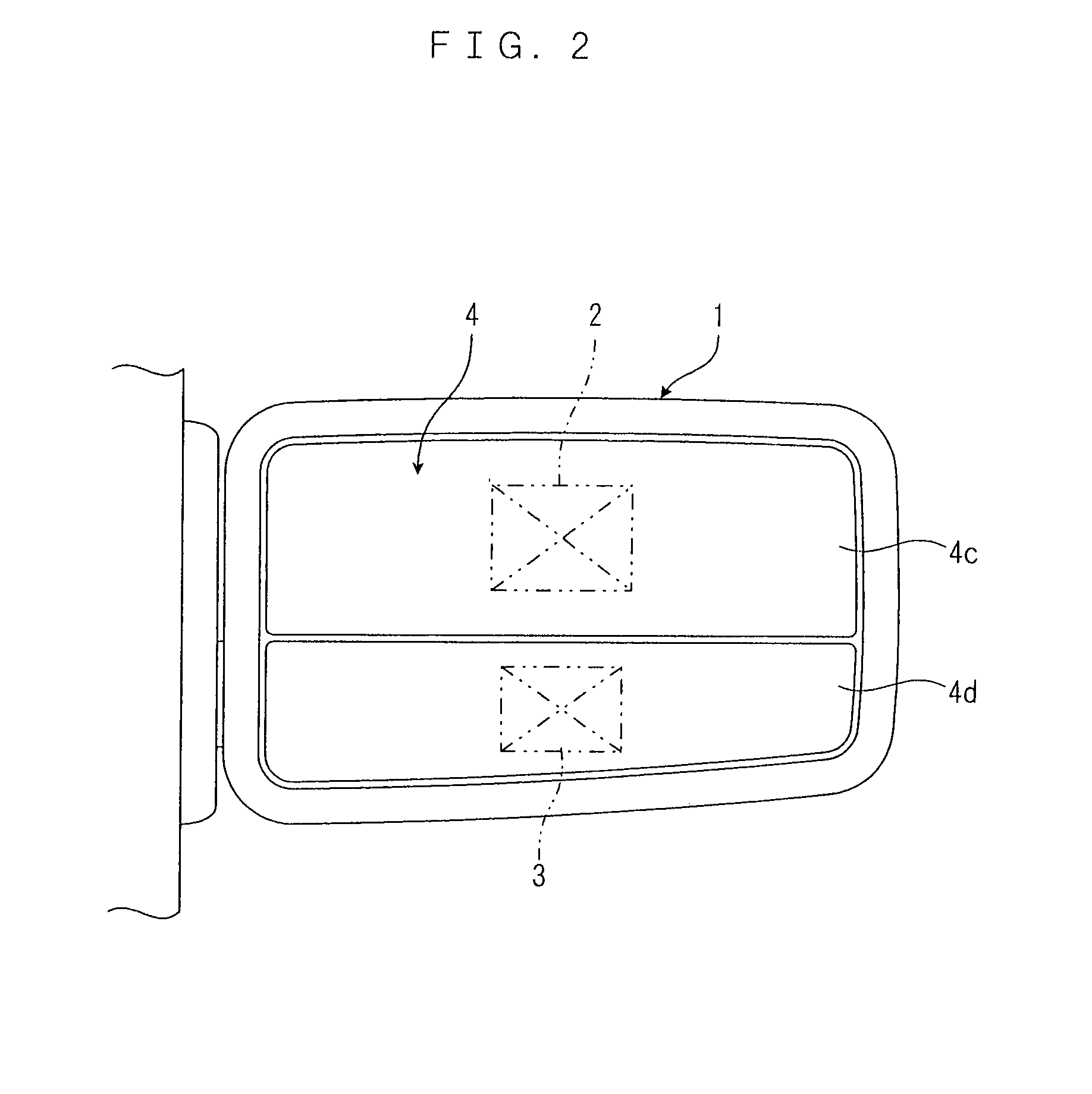
[0036]In a door mirror 1 shown in FIG. 1, its mirror surface 4 for reflecting what is behind a vehicle's body is divided into two parts: an inner part which is nearer to the vehicle's body; and an outer part which is farther away from the vehicle's body, and reflection angles of the two divided mirror surfaces 4a, 4b can be arbitrarily changed respectively by reflection angle adjusting mechanisms 2, 3 mounted on the rear faces of the inner part and outer part divided mirror surfaces 4a, 4b, as shown by dotted lines in FIG. 1. The mechanisms for adjusting the reflection angles of the mirror surfaces are of the same types as the conventionally used ones, and their structures may be explained as follows. The reflection angle adjusting mechanism 2 includes a vertical shaft 2a and a horizontal shaft 2b intersecting crosswise in a cross shape. The vertical shaft 2a is supported by bearings 2c fixed to a casing 1c of the door mirror, while the horizontal shaft 2b is supported by bearings 2...

embodiment 2

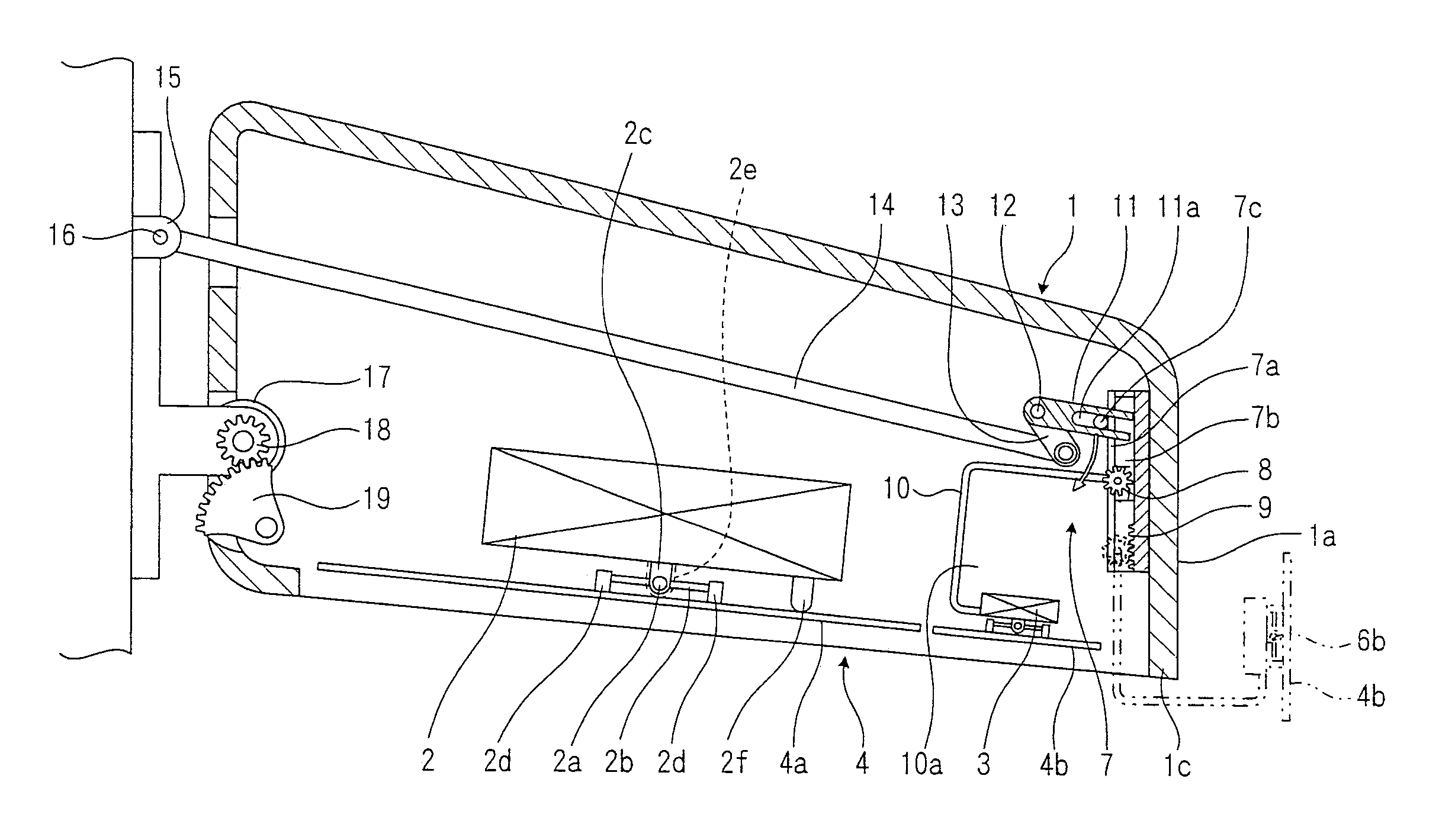
[0044]The door mirror in accordance with embodiment 2, a cross section of which is shown in FIG. 4, is so designed that the reflection angles of the right-hand and left-hand divided mirror surfaces are arbitrarily adjustable by reflection angle adjusting mechanisms 2, 3, and the outer-side mirror surface 4b can be extended, integrally with the reflection angle adjusting mechanism 3, to project outward of a lateral face 1a of the door mirror 1 by a turning mechanism 7 including a slide link mechanism, as shown in FIGS. 5 and 6.

[0045]This turning mechanism 7 is co-axially supported by the shaft of a pinion 8 together with a guide rail 7a provided on the inside face of a casing 1c pendicularly to the mirror surface 4b, a slider 7b that slides along the guide rail 7a, the pinion 8 supported by a shaft perpendicular to the sliding direction of the slider 7b, and a rack 9 provided at the end of the stroke of the slider 7b. A turning arm 10 of which front portion is bent in a reversed J sh...

embodiment 3

[0062]In the door mirror 1 in accordance with embodiment 3, the reflection angles of its divided mirror surfaces 4a, 4b are made adjustable by reflection angle adjusting mechanisms 2, 3 having the same structure as those of embodiment 1 and the divided mirror surface 4b on the outer side, together with the outer side face 1d of the casing 1c, can be turned to project from the casing 1c laterally outward of the outer side face of the door mirror 1.

[0063]In other words, the divided mirror surface 4b of the door mirror 1 in accordance with the embodiment 3 is attached to a curved arm 10b extended from the shaft 12 toward the outer periphery via the reflection angle adjusting mechanism 3, and its outside portion is integrated with a side face member 1d that forms the side face portion of the door mirror 1.

[0064]The shaft 12 is provided with the pulley 22 and the gear rotating shaft 19 of the door mirror 1 is coaxially provided with the pulley 23, the power transmission belt 24 is wound ...


PUM


Abstract

A door mirror which is installed on a motor vehicle's body in such a manner as to project laterally from the vehicle's body so as to reflect on a surface of the mirror what is behind the vehicle's body, wherein the mirror surface of the door mirror is divided into□two parts, and thus divided mirror surfaces are respectively provided with reflection angle adjusting mechanisms so that reflection angles of the divided mirror surfaces can be independently and arbitrarily adjusted, and the divided mirror surface positioned on the outer side can be turned to project laterally from the door mirror to face outward.

Description

FIELD OF THE INVENTION[0001]This invention relates to a door mirror, in particular, to an improvement in a door mirror which is installed on the outside surface of a motor vehicle's door on each side of the driver's seat in such a manner as to project laterally relative to the vehicle's body so that it can reflect what is behind the vehicle's body.BACKGROUND OF THE INVENTION[0002]A door mirror for reflecting what is behind the vehicle's body is installed as a kind of safety device on the outside surface of a motor vehicle's door on each side of the driver's seat.[0003]In general, however, there exists a driver's blind spot behind the vehicle's body, which is not reflected in the door mirror. When altering the reflection angle of the mirror so as to make such blind spot visible, an antinomic problem occurs of permitting a spot having been visible to become a blind spot. Accordingly, to make sure of the safety behind the vehicle's body with the door mirror, care must be taken of the a...

Claims


Application Information

Patent Timeline
Patent Type & Authority Patents(United States)
IPC IPC(8): G02B7/182B60R1/08B60R1/06B60R1/072
CPCB60R1/081B60R1/06
Inventor YAMABE, HIDEYASU
Owner ATORASU OOTO
Learn More