System for joining polarization-maintaining optical fiber waveguides

a technology of optical fiber waveguides and polarization-maintaining optical fibers, applied in the direction of optical waveguide light guides, instruments, optics, etc., can solve the problems of large mechanical splice loss, and relatively high mechanical splice loss, so as to maximize the measured intensity signal, optimize alignment, and improve the alignment

Inactive Publication Date: 2006-01-10
AURORA INSTR
View PDF36 Cites 12 Cited by
  • Summary
  • Abstract
  • Description
  • Claims
  • Application Information

AI Technical Summary

Benefits of technology

[0031]Such systems in some embodiments employ a profile alignment (PAS) system that employs a compact, imaging optical system incorporated in a fusion splicing head of the system. In the PAS technique, the relative positions of the fiber ends is estimated using electronic analysis of optical images taken in two non-coincident, preferably orthogonal, directions. Motion means are then used to move the fibers accordingly into lateral alignment. Preferably the PAS system is operated iteratively to further improve the alignment.
[0032]More preferably, embodiments of the system incorporate a local injection and detection (LID) system in carrying out the alignment. In the LID technique, optimal alignment is signaled by maximization of the transmission of light across the interface between the fibers.
[0034]Advantageously, the present system in its various embodiments allows the fibers to be efficiently and precisely aligned prior to fusion. Accurate alignment advantageously results in a low-loss joint, i.e., a joint through which a light signal may propagate with its signal strength and mode integrity maintained, because the attenuation and back reflection attributable to the joint are rendered extremely low. Preferably, joints made with the present apparatus have an average loss of less than about 0.03 dB, and more preferably, an average of less than about 0.02 dB. Most preferably, every joint has a loss of less than about 0.02 dB.
[0035]The method and apparatus of the present invention afford significant advantages over previous alignment systems. Inasmuch as the fibers appointed for alignment need not be coupled at their far ends to source and detector, the alignment set-up procedure is less complex. Coupling is readily effected in an accurate, reliable manner without need of skilled personnel, and the time and cost required for splicing polarization-maintaining single mode fiber is reduced.

Problems solved by technology

Alignment of fibers is a crucial part of the preparation for any splicing operation, but is especially challenging for single mode fibers that have small core diameter.
However, even in the best case, a mechanical splice has relatively high and undesirable insertion loss, typically 0.20 dB.
In addition, mechanical splices are generally weaker than the underlying fiber and are notoriously vulnerable to degradation of the optical quality of the splice over time, especially under adverse environmental conditions such as varying temperatures and high humidity.
Mechanical splices are generally regarded as being temporary expedients at best and are not useful for high bandwidth systems or permanent joints.
This required precision of alignment presents a substantial technical challenge, especially with single-mode fibers having cores approximately 9 μm diameter.
These purely mechanical approaches do not reliably produce splices that maintain less than 0.10 dB loss and so are ill suited for the demands of advanced, high-bandwidth communications systems.
However, the diffraction limit and pixel size of available electro-optic detectors restricts the precision achievable with PAS, even in systems based on visible light with wavelengths of about 400–700 nm.
This particularly compromises the effectiveness of PAS in aligning small diameter, single mode fibers.
If the mode alignment is off by more than about 1 degree very serious losses and dispersion occur.
Not only does the projected power become divided between the two orthogonal modes of the receiving fiber, but the coupling into the originally-excited mode is very poor.
Rotational alignment is, alternatively, accomplished by the following methods: (1) coupled power monitoring, which is difficult and time consuming, and requires expensive input and output source and detector alignments; (2) axial imaging, which requires the fiber to have obvious and distinctive features; and (3) lateral imaging, in which the fiber must have obvious internal features amenable to a precisely-alignable image.
With the first (power injection / detection) fiber alignment method, the set-up required to power and monitor the fibers is difficult and time-consuming to establish.
Highly-skilled personnel are required; and the splicing procedure is itself time-consuming.
If more than one pair of fibers is to be spliced, the process time and procedural difficulty increase dramatically.
If alignment is to be automatic, the system therefore requires sophisticated, expensive, and delicate image processing technology.
Thus methods (2) and (3) are both difficult to implement and limited in applicability to a small proportion of the available PM fibers.

Method used


Image

  • System for joining polarization-maintaining optical fiber waveguides
  • System for joining polarization-maintaining optical fiber waveguides
  • System for joining polarization-maintaining optical fiber waveguides

Examples


Embodiment Construction

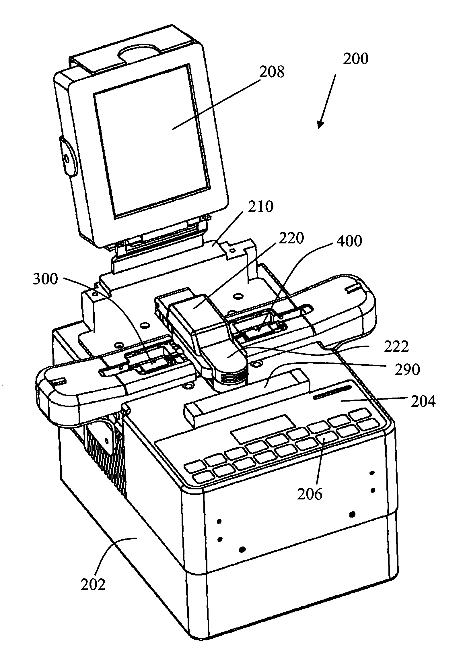
[0048]The present invention is directed to an apparatus and system for producing a durable fusion splice between a first and a second polarization-maintaining optical fiber. The joined fiber advantageously exhibits low attenuation. Advantageously the present system employs an adaptive technique to optimize the lateral and azimuthal alignment of the fibers prior to fusion, whereby the insertion loss and mode cross-coupling of the splice are minimized.

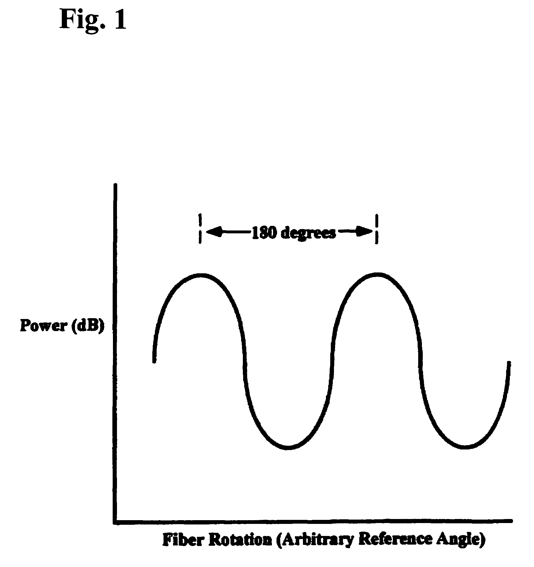
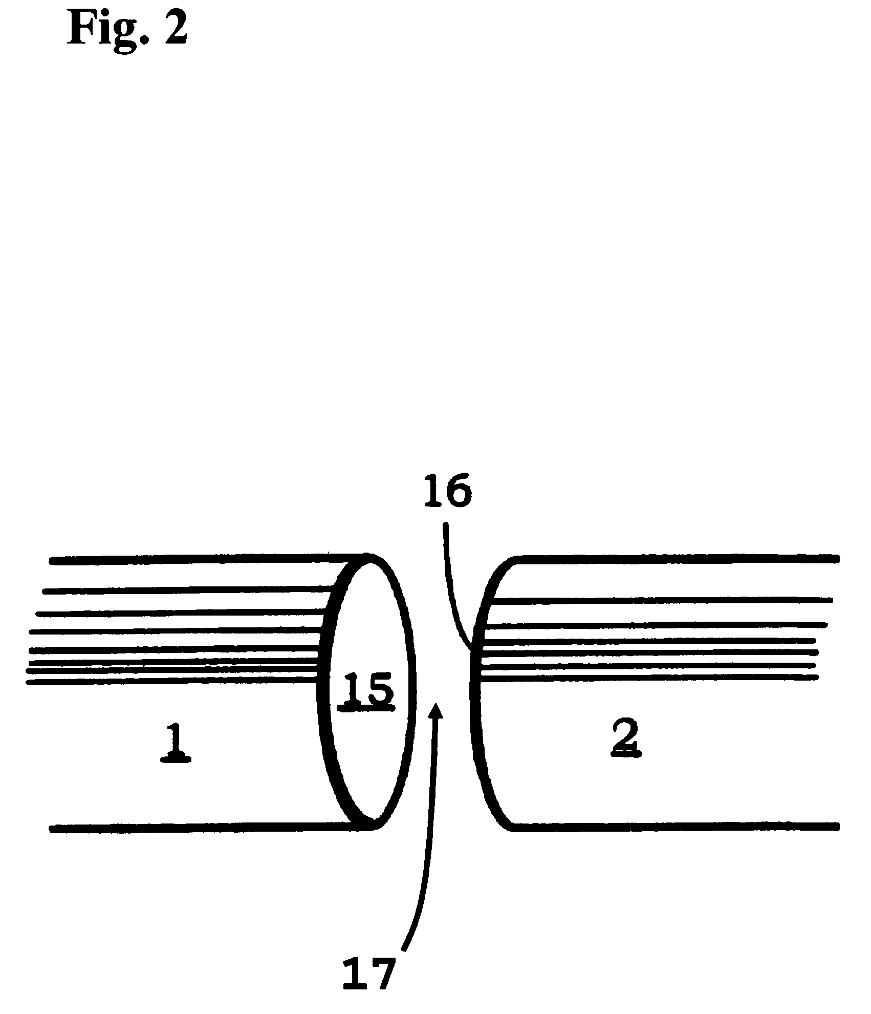
[0049]Polarization-maintaining fibers exhibit asymmetric stresses. In most such fibers the stresses are created deliberately, as the decoupling of the two degenerate polarized modes is achieved by refractive index changes due to stress. The unequal stresses result in very different propagation constants for the two orthogonal modes, which reduce cross-coupling to a very low level, typically −20 to −30 dB. The asymmetric stresses are achieved by the use of an elliptical inner cladding layer (3M and Hitachi), a bow-tie-shaped pair of regio...


PUM


Abstract

A splicing system for joining polarization-maintaining, single mode optical fibers produces durable fusion splices that have low transmission loss and maintain mode integrity. The system employs active optical techniques such as profile alignment or local injection and detection to achieve optimized lateral alignment of the fibers prior to fusion. Azimuthal alignment is performed using a transverse, polarized light illumination and detection system. Each fiber is rotated azimuthally to determine a transverse intensity function. The transverse intensity functions of the respective fibers are cross-correlated to determine a relative orientation that matches the polarization axes of the fibers. After the relative position of the fibers is manipulated laterally, axially, and azimuthally, the fibers are fusion spliced using an electric arc discharge. The accurate alignment achievable using the transverse illumination mechanism to drive adaptive fiber positioning affords a method for reliably producing low loss, mode-matched splices. Simplicity of design and operation make the system rugged and enable accurate alignment and low loss fusion of fibers under adverse working conditions.

Description

[0001]This Application claims the benefit of Application No. 60 / 456,968, filed Mar. 25, 2003.BACKGROUND OF THE INVENTION[0002]1. Field of the Invention[0003]This invention relates to an apparatus for joining optical fiber waveguides; and more particularly, to a system for adaptively positioning and orienting polarization-maintaining fibers for fusion splicing, so that the transmission loss of the joined fiber is minimized and the mode integrity is maintained.[0004]2. Description of the Prior Art[0005]Transmission of data by optical fiber waveguides, also called fiber optics or optical fibers, has become ubiquitous in the telecommunications and computer industries. Digital information in an electronic system is converted into a series of pulses of light generated by lasers or light emitting diodes (LED's), which are injected into long fibers of glass or polymeric materials. The fibers are capable of propagating the light with extremely low losses and acceptably low dispersion, whereb...

Claims


Application Information

Patent Timeline
Patent Type & Authority Patents(United States)
IPC IPC(8): G02B6/38G02B6/10G02B6/255G02B6/34
CPCG02B6/2551G02B6/105
Inventor BUSH, SIMON P.CABATO, NELLIE L.GOMES, ALAN D.HARRIS, S. DYERTIPTON, DOUGLAS F.WESSON, LAURENCE N.CHAU, HOLAM
Owner AURORA INSTR
Why Eureka
Try Eureka