Laser beam machining device

a technology of machining device and laser beam, which is applied in the direction of metal working apparatus, manufacturing tools, welding/soldering/cutting articles, etc., can solve the problems of difficult to improve the productivity easily and cheaply with a single beam, and the strict requirements for processing the hole in terms of the dispersion of the hole diameter, so as to achieve the effect of improving the productivity less expensiv

Inactive Publication Date: 2006-01-10
MITSUBISHI ELECTRIC CORP
View PDF9 Cites 44 Cited by
  • Summary
  • Abstract
  • Description
  • Claims
  • Application Information

AI Technical Summary

Benefits of technology

[0019]This invention has been achieved to solve the above-mentioned problems, and it is an object of the invention to provide a laser material processing apparatus in which a difference in the energy or quality between separated l

Problems solved by technology

However, it takes a lot of time to design, and it is required to change the specification of the very expensive fθ lens or the design of the overall optical system, whereby it was difficult to improve the productivity easily and cheaply with a single beam.
Therefore, there is the possibility that the strict requirements for processing the h

Method used


Image

  • Laser beam machining device
  • Laser beam machining device
  • Laser beam machining device

Examples


embodiment 1

[0041

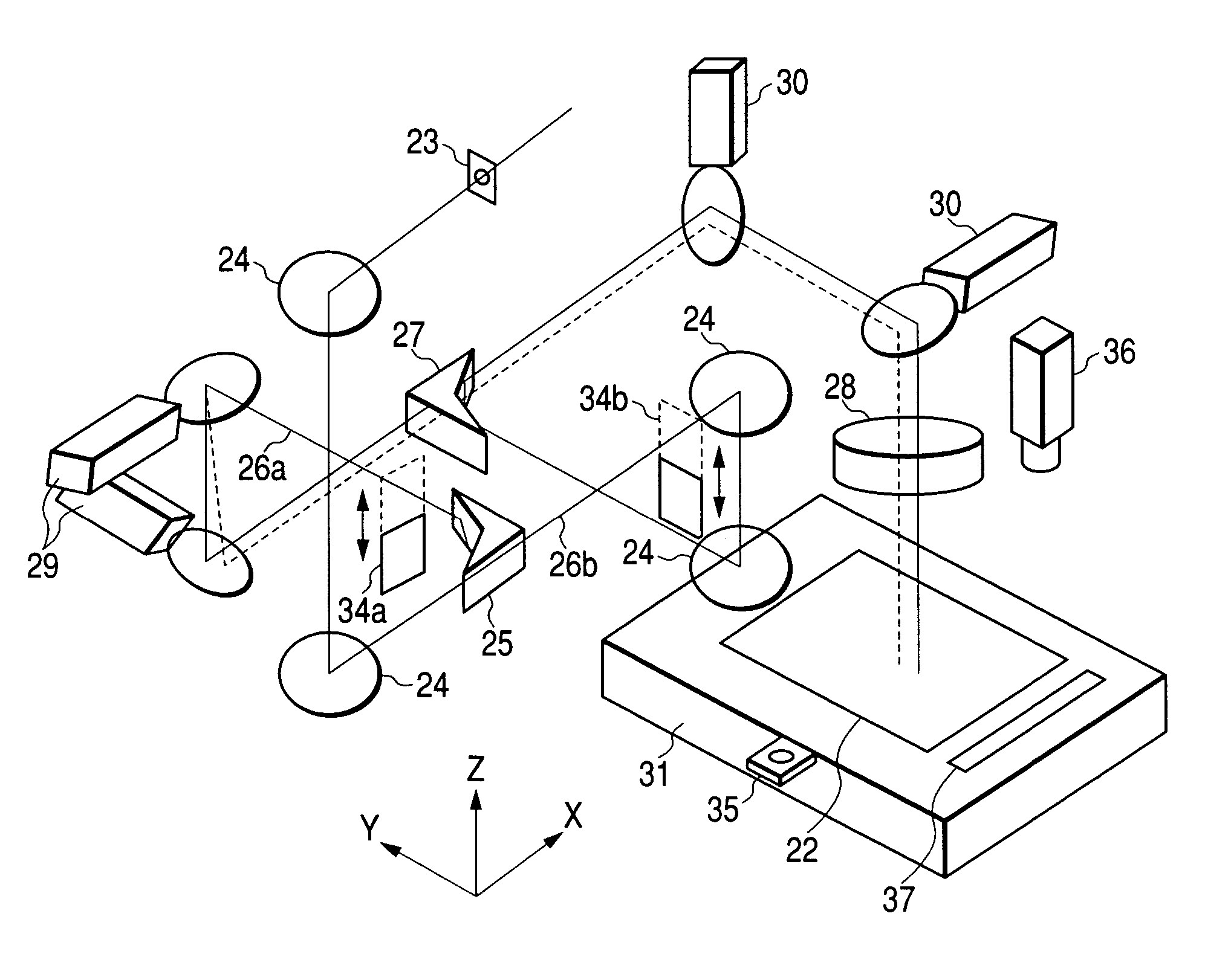
[0042]FIG. 1 is a schematic constitutional view showing a laser material processing apparatus according to an embodiment of the present invention.

[0043]In FIG. 1, reference numeral 22 denotes a workpiece such as a printed board, 23 denotes a mask for forming an image to transfer a desired processing shape (e.g., circle) onto the workpiece 22, 24 denotes a plurality of mirrors for reflecting a laser beam along the optical path, 25 denotes a first polarized beam splitter as first polarizing means for separating a laser light, 26a denotes a laser beam reflected from the first polarized beam splitter, 26b denotes a laser beam transmitted through the first polarized beam splitter, 27 denotes a second polarized beam splitter as second polarizing means for transmitting the laser beam 26a and reflecting the laser beam 26b, 28 denotes an fθ lens for focusing the laser beams 26a and 26b onto the workpiece 22, 29 denotes a first galvano scanner for scanning the laser beam 26a biaxially to...

embodiment 2

[0092

[0093]After separation into laser beams by the polarized beam splitter, the laser beams are circularly polarized again, or incident on the polarized beam splitter at an angle of 45° with respect to the polarization directions of reflection and transmission, whereby the separation into laser beams is repeated, and the machining is made using not only two beams but also 2n laser beams.

[0094]FIG. 6 is a schematic constitutional view showing an example of the laser material processing apparatus in which third polarizing means is added to make the machining using four laser beams.

[0095]In the constitution as shown in FIG. 6, a laser light of circular polarization or linear polarization is oscillated and conducted from the laser oscillator, not shown, and separated into laser beams by a third polarized beam splitter 38. The optical path is constituted so that the polarization direction of a laser beam 26 transmitted through the third polarized beam splitter 38 and the polarization di...


PUM

PropertyMeasurementUnit
Transmissionaaaaaaaaaa
Energyaaaaaaaaaa
Optical propertiesaaaaaaaaaa

Abstract

A laser material processing apparatus for processing a workpiece (22) in such a way as to separate one laser light (26) into two laser beams (26a, 26b) via first polarizer (25), one laser beam being passed via the mirrors (24), the other laser beam being scanned biaxially by a first galvano scanner (29), and conduct two laser beams (26a, 26b) to a second polarizer (27) for scanning via a second galvano scanner (30), wherein an optical path is constituted such that the laser beam (26b) transmitted through the first polarizer (25) is reflected by the second polarizer (27), and the laser beam (26a) reflected by the first polarizer (25) is transmitted through the second polarizer (27).

Description

TECHNICAL FIELD[0001]The present invention relates to a laser material processing apparatus mainly intended for drilling the workpiece such as a printed board to improve the productivity.BACKGROUND ART[0002]FIG. 8 is a schematic constitutional view showing the conventional laser material processing apparatus for drilling.[0003]In FIG. 8, reference numeral 1 denotes a workpiece such as a printed board, 2 denotes a laser beam for drilling the workpiece 1 to make a via hole or through hole, 3 denotes a laser oscillator for oscillating the laser beam 2, 4 denotes a plurality of mirrors for reflecting the laser beam 2 along the optical path, 5 and 6 denote a galvano scanner for scanning the laser beam 2, 7 denotes an fθ lens for focusing the laser beam 2 on the workpiece 1, and 8 denotes an XY stage for moving the workpiece 1.[0004]In the typical laser material processing apparatus for drilling, the laser beam 2 oscillated from the laser oscillator 3 is conducted via a necessary mask and...

Claims


Application Information

Patent Timeline
IPC IPC(8): B23K26/06B23K26/064B23K26/067B23K26/382
CPCB23K26/0608B23K26/067B23K26/4025B23K26/381B23K2201/42B23K26/382B23K2101/42B23K2103/50H05K3/00
Inventor KUROIWA, TADASHIIJIMA, KENICHIKOBAYASHI, NOBUTAKA
Owner MITSUBISHI ELECTRIC CORP
Why Eureka
Try Eureka