Method and apparatus for controlling a variable optical attenuator in an optical network

a variable optical attenuator and optical network technology, applied in the field of optical telecommunications networks, can solve the problems of increasing bit error rate, affecting the accuracy of optical network control, so as to achieve the effect of high attenuation and convenient adjustmen

Active Publication Date: 2006-01-17
WSOU INVESTMENTS LLC +2
View PDF4 Cites 13 Cited by
  • Summary
  • Abstract
  • Description
  • Claims
  • Application Information

AI Technical Summary

Benefits of technology

[0013]It is an object of the present invention to provide method and apparatus for controlling attenuation for a variable optical attenuator (VOA) in optical systems and networks, which would provide suf

Problems solved by technology

As it is well known, network re-configurations, link or node failures, protection switching, and add/drop multiplexing may cause abrupt changes of the power levels of signals propagating in optical telecommunications networks.
This may cause degradation in signal-to-noise ratios (SNR) and increase in bit error rates (BER).
Generally, the VOA control loop mechanism is not fast enough to provide the required attenuation to prevent damage to downstream optical components in the optical network, which can occur on the sub-millisecond timescale.
The plurality of optical channels momentarily suffers a drop in optical power, which may lead to excessive BER on these channels.
The attenuation of the VOA is not always adequate in this case to eliminate the power spikes that could damage t

Method used


Image

  • Method and apparatus for controlling a variable optical attenuator in an optical network
  • Method and apparatus for controlling a variable optical attenuator in an optical network
  • Method and apparatus for controlling a variable optical attenuator in an optical network

Examples


first embodiment

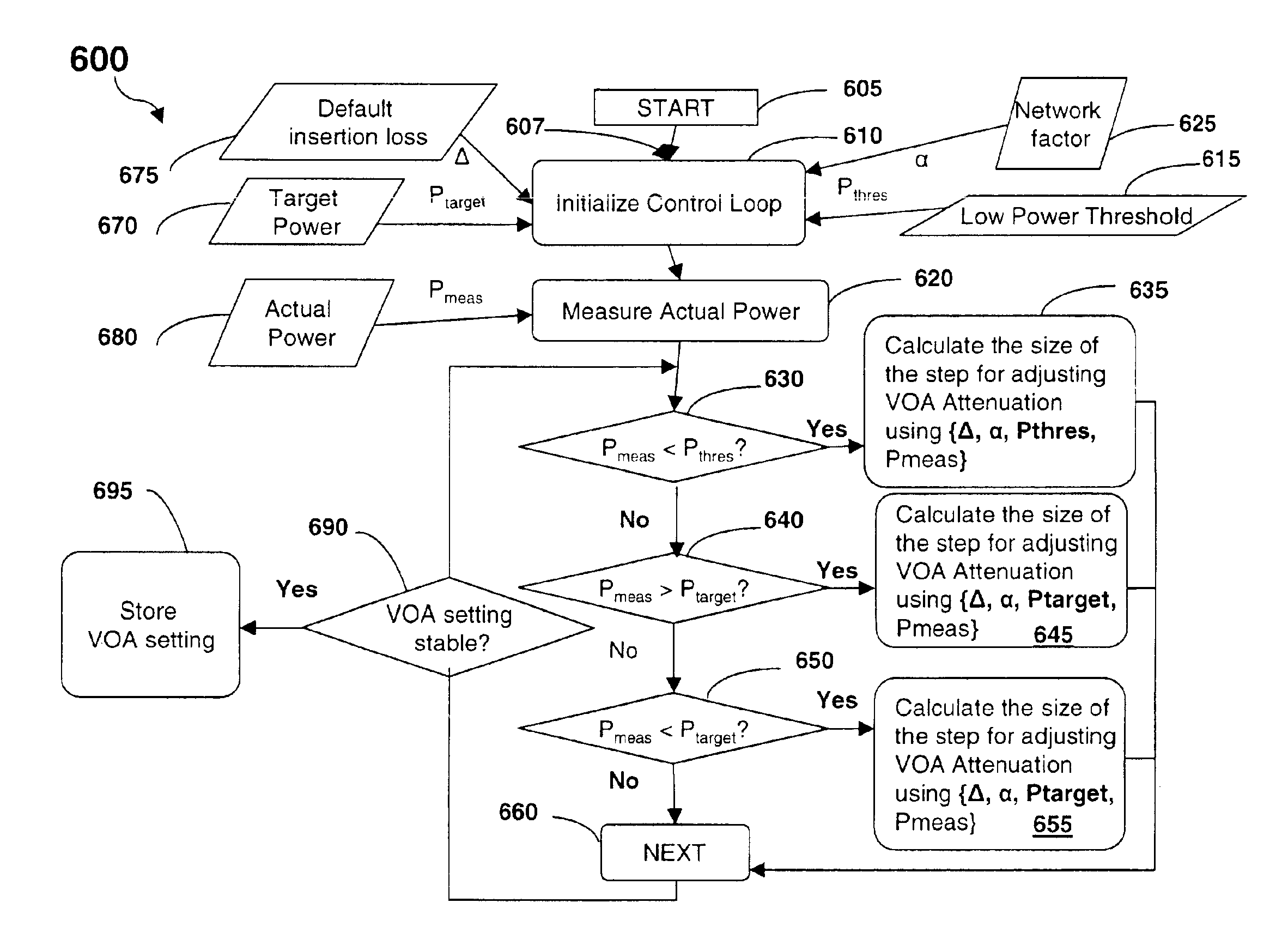
[0045]Thus, in accordance with the present invention, the dynamic VOA attenuation setting method, incorporated on the smart microcontroller, manages the VOA control loop open and closed operations as follows:[0046]Step 1: initializing the parameters {Δ, α, Ptarget, Pmeas, Pthres}.[0047]Step 2: setting up VOA attenuation to target power {Ptarget} when VOA control loop is in open loop mode:[0048]smart microcontroller updates the VOA attenuation setting,[0049]VOA control loop is closed once the input to the VOA has stabilized, and[0050]VOA setting is adjusted until the target output power is reached.[0051]Step 3: if the measured power {Pmeas} at the output of the VOA {Poutput} is below a LOS power threshold {Pthres}:[0052]smart microcontroller computes the VSI, wherein the VSI is given by the following formula: VSI=Δ⁢ +∑i=1n⁢ ⁢α⁡(i)·[{Pthres}-{Pmeas}]n[0053]controller changes the VOA attenuation by said VSI,[0054]VOA control loop closes and converges on the new optical output power,[00...

second embodiment

[0065]FIG. 7 shows an apparatus 700 for controlling attenuation for a variable optical attenuator (VOA) 710 inserted in an optical path of an optical signal propagating in an optical network according to the invention. In FIG. 7, a tap coupler 720 leads the VOA 710 with a tap monitor 730. The tap coupler 720 is for detecting the power of the optical signal 701 at an input to the VOA 710 and the tap monitor 730 is for measuring the power of the optical signal 701 at an input to the VOA 710. The optical tap coupler 720 is calibrated properly to accurately report the input power 701. As described before, calibration of the tap coupler 720 and tap monitor 730 are done during the manufacturing process. The LOS power threshold {Pthres} and target power {Ptarget} are calibrated during commissioning of the installed system to meet the requirements of the optical network. The tap coupler 720 output is sampled with an analogue-to-digital converter (ADC) 735 and the result is processed by a sm...

third embodiment

[0085]FIG. 8 shows an apparatus 800 for controlling attenuation for a variable optical attenuator (VOA) 810 inserted in an optical path of an optical signal propagating in an optical network according to the invention. In FIG. 8, a tap coupler 820 leads the VOA 810 with a tap monitor 830 for detecting and measuring the power of the optical signal 801 at the input to the VOA 810, respectively. The tap coupler 820 output is sampled with an analogue-to-digital converter (ADC) 835 and the result is processed by a smart microcontroller 840. A tap coupler 860 follows the VOA 810 with a tap monitor 850 for detecting and measuring the power of the optical signal 802 at the output of the VOA 810, respectively. The tap coupler 860 output is sampled with an analogue-to-digital converter (ADC) 855 and the result is processed by a smart microcontroller 840. The attenuation of the VOA 810 is set by the smart microcontroller via a digital-to-analogue converter (DAC) 845. The optical tap coupler 82...


PUM


Abstract

This invention describes a method for controlling attenuation for a variable optical attenuator (VOA) inserted in an optical path of an optical signal propagating in an optical network, comprising the steps of measuring power of the optical signal at the VOA; comparing the measured power with a target power; and if the measured power differs from the target power, changing the attenuation of the VOA in one or more variable size intervals (VSI) so that the power of the optical signal substantially equals to the target power, wherein the VSI being a function of the measured power and target power. The method further comprises the step of comparing the measured power with a Loss-of-signal (LOS) power threshold, and if the measured power is less than the LOS power threshold, changing the attenuation of the VOA in one or more variable size intervals so that the power of the optical signal substantially higher than the LOS power threshold, wherein the size of the variable interval being a function of the measured power and the LOS power threshold. The method dynamically computes a VSI, updates the VOA setting by said VSI, and manages a combination of open and closed VOA control loops to maintain the target power attenuation of the VOA The corresponding apparatus for controlling the VOA is also provided.

Description

RELATED APPLICATION[0001]This application claims priority from U.S. Provisional Patent Application Ser. No. 60 / 430,972 to Bierman, R. M., entitled “Method and Apparatus for Power Control in an Optical system”, and filed on Dec. 5, 2002.FIELD OF THE INVENTION[0002]This invention relates generally to optical telecommunications networks and, in particular, to a method for controlling attenuation for a variable optical attenuator (VOA) inserted in an optical path of an optical signal propagating in an optical network.BACKGROUND OF THE INVENTION[0003]As it is well known, network re-configurations, link or node failures, protection switching, and add / drop multiplexing may cause abrupt changes of the power levels of signals propagating in optical telecommunications networks. This may cause degradation in signal-to-noise ratios (SNR) and increase in bit error rates (BER). To compensate for the unexpected power variations, a variable optical attenuator (VOA) is usually inserted (coupled with...

Claims


Application Information

Patent Timeline
IPC IPC(8): G02B6/00H04B10/08H04J14/02
CPCH04B10/077H04B10/07955H04J14/0221
Inventor BIERMAN, ROBERT MICHAELMOHARRAM, OMAYMADONNELLY, VICTORIA
Owner WSOU INVESTMENTS LLC
Why Eureka
Try Eureka