System and method for power saving delay locked loop control by selectively locking delay interval

Inactive Publication Date: 2006-01-17
ROUND ROCK RES LLC
View PDF14 Cites 58 Cited by
  • Summary
  • Abstract
  • Description
  • Claims
  • Application Information

AI Technical Summary

Benefits of technology

[0015]Through the addition of logic sensing when a DRAM device will not imminently be called upon to output data and allow an appropriate delay interval for the DLL delay interval to stabilize, the DLL delay interval can be locked to stop the DLL from wasting power in unnecessarily switching to synchronize with the system clock. However, waiting for the DLL delay interval to stabilize before locking the delay interval better allows the DLL to immediately and effectively resume operations when the DLL

Problems solved by technology

Moreover, at such high speeds, concerns arise not only from the possibility of data taking too long to become available at a certain point in a device, but also from the possibility that data may be available too soon.
If one digital device were, for example, to be operating one clock pulse ahead or behind a storage device from which the device receives data, the results generated by the device might be based on erroneous operands.
As a digital system grows in size, complexity, and number of devices it comprises, the effect of the heat generated by the devices affects the regularity of the phase of the clock signal.
Similarly, the switching of the many devices causes fluctuations in the supply voltage to the circuit, which in turn affects the supply voltage available to the devices and thereby affects the phase of the clock pulses.
Literally, as a circuit becomes sufficiently complex, it becomes virtually impossible for a single clock source to pulse the entire circuit; switching of devices pulsed by

Method used


Image

  • System and method for power saving delay locked loop control by selectively locking delay interval
  • System and method for power saving delay locked loop control by selectively locking delay interval
  • System and method for power saving delay locked loop control by selectively locking delay interval

Examples


Embodiment Construction

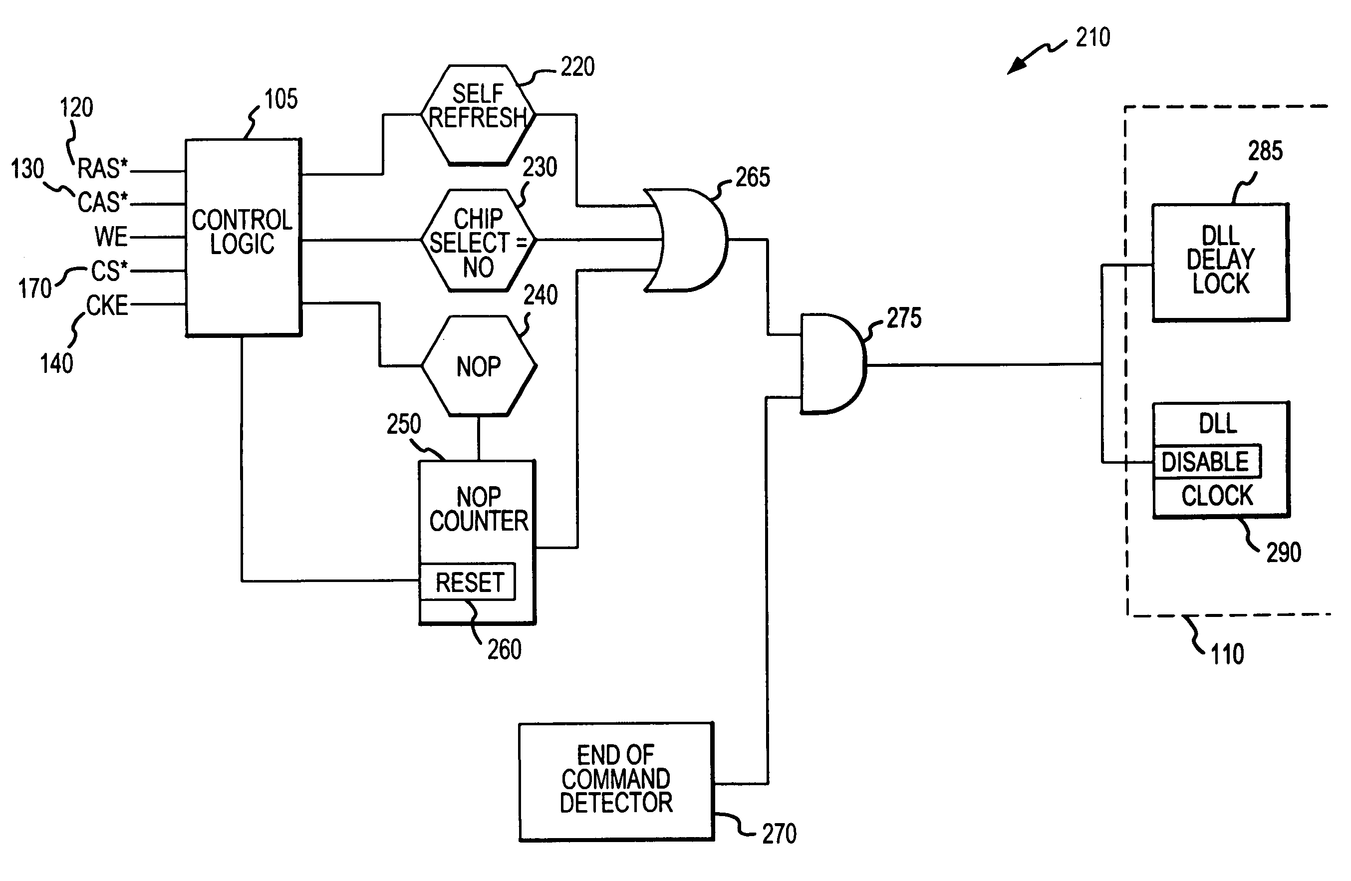
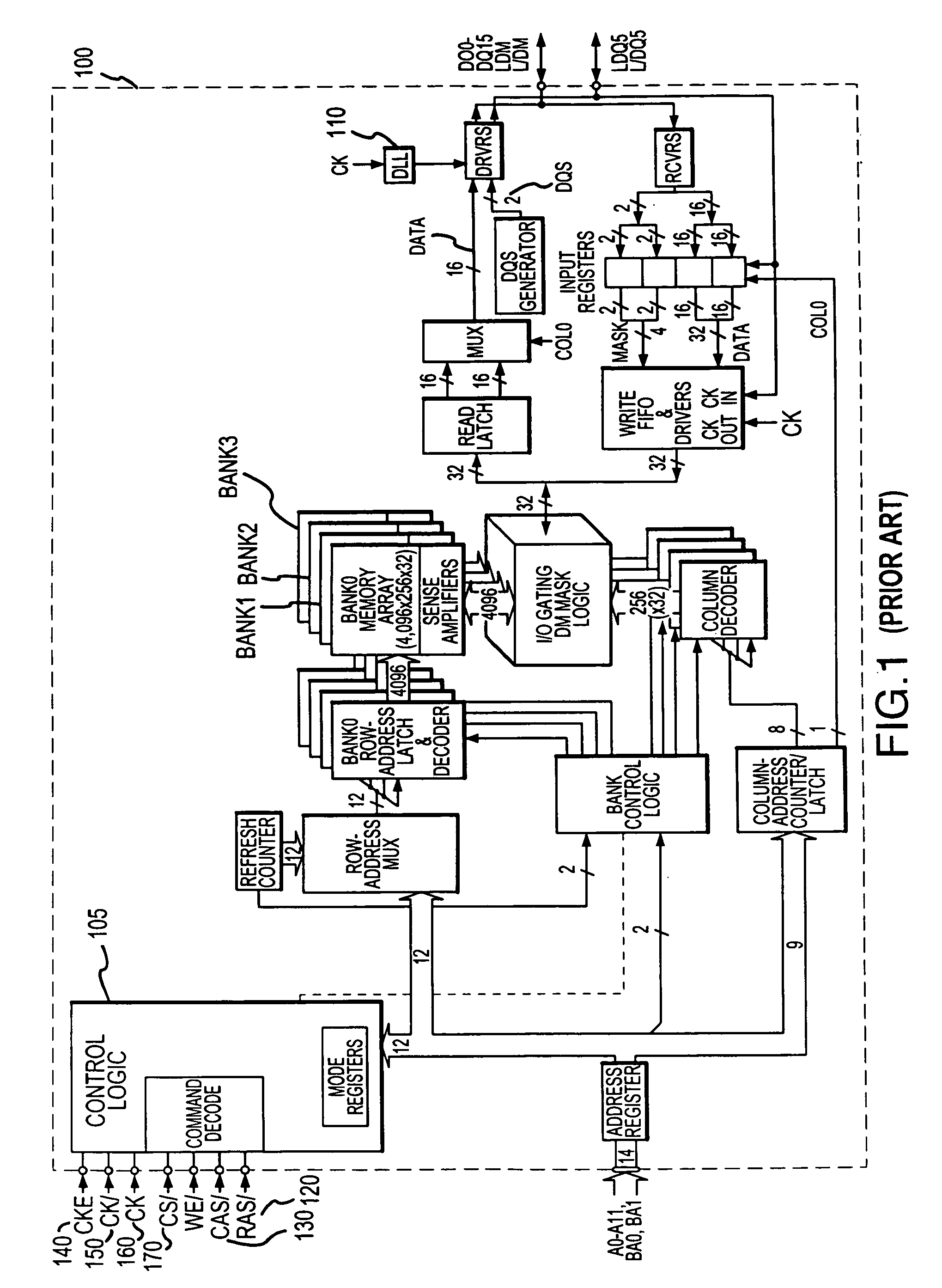
[0020]In addition to when the DRAM device 100 (FIG. 1) is in self-refresh mode, there are other times when power ordinarily wasted on DLL 110 switching might be saved. The DRAM device 100, may be in an operational mode but still neither reading nor writing data, nor being auto-refreshed by the system. For example, the DLL 110 need not be actively synchronizing the output of the DRAM device 100 when the DRAM device is “deselected.” The DRAM device 100 is deselected when the CS* 170 (chip select—low enable) control line is driven high, which signals the DRAM device 100 will not be used to provide data until such time as the CS* 170 control line is once more driven low. Comparably, the DRAM device 100 might “infer” that it will not imminently be called upon to read or write data when the DRAM device 100 has received a number of sequential NOP or “no operation” commands. Depending on whether the system clock speed is slower or faster, after receiving two or three NOP commands, respectiv...


PUM


Abstract

The delay locked loop (“DLL”) delay interval can be locked to stop the DLL from wasting power in unnecessarily switching to synchronize the device with the DLL is associated to the system clock. This is achieved by adding logic sensing when a DRAM device will not imminently be called upon to output data and when the device has stabilized. Waiting for the DLL delay interval to stabilize before locking the delay interval still allows the DLL to immediately and effectively resume operations when the DLL is needed to synchronize the output of the DRAM device with the system clock. The DLL delay interval can be locked, together with the DLL clock, after the DRAM device is deselected by the chip select control line, after a number of no operation commands have been received, and/or after any command issued to the DRAM device has been completed.

Description

TECHNICAL FIELD[0001]The present invention is directed to random access memory (“RAM”) devices and other devices employing delay locked look (“DLL”) subsystems. More particularly, the present invention is directed to a system and method allowing devices employing DLL subsystems to save power when the DLL subsystem is not needed.BACKGROUND OF THE INVENTION[0002]In an era when microprocessors and supporting devices are commonly rated at gigahertz clock speeds, the synchronization in timing between digital devices becomes ever more critical. At high speeds, even the propagation time required for a signal traveling from one digital device to another, or even from one part of a digital device to another part of the same device, becomes both a design and operational concern. Moreover, at such high speeds, concerns arise not only from the possibility of data taking too long to become available at a certain point in a device, but also from the possibility that data may be available too soon...

Claims


Application Information

Patent Timeline
IPC IPC(8): G06F1/04G11C8/00G06F1/32G11C7/22G11C11/4076
CPCG06F1/3228G06F1/3275G11C7/22G11C11/40615G11C11/4076G11C7/222Y02B60/1228Y02D10/00
Inventor DREXLER, ADRIAN J.
Owner ROUND ROCK RES LLC
Why Eureka
Try Eureka