Turbine moving blade and gas turbine

a technology of moving blades and gas turbines, which is applied in the direction of liquid fuel engines, vessel construction, marine propulsion, etc., can solve the problems of reducing the life of the turbine moving blade b>50/b>, the inability to simply raise the turbine inlet temperature, and the inability to maintain the turbine moving blade. , to achieve the effect of improving the thermal reducing the maintenance cost of the turbine moving blade, and improving the operating efficiency of the gas turbin

Inactive Publication Date: 2006-01-24
MITSUBISHI HITACHIPOWER SYST LTD
View PDF19 Cites 18 Cited by
  • Summary
  • Abstract
  • Description
  • Claims
  • Application Information

AI Technical Summary

Benefits of technology

[0011]In consideration of these circumstances, the object of the present invention is to provide a turbine moving blade that has high heat resistance and can be used for a long time, improve the thermal efficiency of gas turbines and improve their operating efficiency by improving the cooling efficiency of the turbine moving blade.
[0013]According to the turbine moving blade, among the cooling medium trailing edge blow-out openings provided in a row at a plurality of locations from the vicinity of the blade base to the vicinity of the blade tip along the blade trailing edge of the turbine moving blade, since the opening area of the blade tip trailing edge blow-out opening (tip flag feature) located in the vicinity of the blade tip is set to be larger than the opening area of the other trailing edge blow-out openings, the flow volume of cooling medium blown out from the blade tip trailing edge blow-out opening is increased greater than the other trailing edge blow-out openings, thereby improving cooling effects at the blade tip. In other words, since the decrease in cooling effects caused by the temperature rise of the cooling medium at the blade tip of the turbine moving blade is negated by the improvement in cooling effects resulting from increasing the cooling medium flow volume at the blade tip, cooling effects are improved. As a result, the heat resistance of the turbine moving blade can be improved, the occurrence of burning and chipping can be prevented, and the lifetime of the turbine moving blade can be extended.
[0015]According to the turbine moving blade, cooling medium that flows through the internal flow path having a U-turn section and the turbulators are turned in the opposite direction by the U-turn section while being agitated by turbulators provided at an inclination. At this time, since the turbulators are provided on the upstream side of the U-turn section so as to be inclined upstream to downstream when facing from a wall continuous with the outside wall of the U-turn section towards a wall continuous with the inside wall, pressure loss is reduced in the U-turn section. In other words, although the flow of cooling medium on the inside wall of the U-turn section is normally difficult due to centrifugal force resulting from the cooling medium being turned in the opposite direction, since turbulators are provided on the upstream side of the U-turn section so as to force the cooling medium towards the inside of the U-turn section, the cooling medium flows easily through the U-turn section thereby decreasing pressure loss. As a result, the flow volume of cooling medium that flows through the internal flow path can be increased, thereby allowing cooling efficiency to be improved.
[0017]According to the turbine moving blade, a film cooling effect is obtained in the vicinity of the blade tip as a result of discharging cooling medium from tip holes opened in the blade surface in the vicinity of the blade tip, and since these tip holes are inclined towards the direction of the blade tip and have a fan-shaped opening that expands towards the direction of the blade tip, cooling medium flows easier to the wing tip than in the prior art, and the effect of film cooling is improved at the blade tip. As a result, satisfactory cooling effects are obtained at the blade tip, thereby making it possible to prevent burning and chipping at the blade tip.
[0019]According to the gas turbine, since it comprises the above-mentioned turbine moving blade, burning and chipping of the turbine moving blade is inhibited even if the temperature of the combustion gas (fluid) for operation at the turbine inlet reaches a high temperature. As a result, since the temperature of the combustion gas for operation at the turbine inlet can be raised to a high temperature, together with it being possible to improve the thermal efficiency of the gas turbine, since maintenance of the turbine moving blade can also be reduced, the operating efficiency of the gas turbine can be improved.

Problems solved by technology

On the other hand, since the heat resistance performance of the turbine moving blades, stationary blades and other members exposed to combustion gas is restricted by the physical properties of their materials, it is not possible to simply raise the turbine inlet temperature.
However, in the turbine moving blade 50 as described above, although various contrivances are made to ensure heat resistance performance, in the case cooling is still not adequate, there was the problem of burning and chipping at various locations of the turbine moving blade 50 such as in the blade tips and the blade surfaces.
As a result, not only is the lifetime of the turbine moving blade 50 shortened and the operating efficiency of a gas turbine using this turbine blade 50 decreased, but there was also the problem of a decrease in thermal efficiency.

Method used


Image

  • Turbine moving blade and gas turbine
  • Turbine moving blade and gas turbine
  • Turbine moving blade and gas turbine

Examples


Embodiment Construction

[0028]The following provides an explanation of a mode for carrying out the present invention with reference to the drawings.

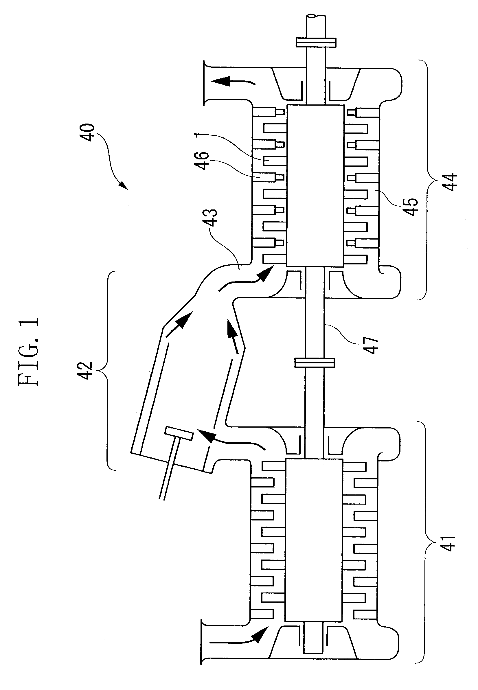
[0029]FIG. 1 is a cross-sectional view showing the general composition of gas turbine 40 of this embodiment. Air compressed with a compressor 41 is combusted after mixing with fuel in a combustion chamber 42, and this combustion gas (fluid) is then sent inside of a turbine 44 from a turbine inlet 43. In a combustion gas flow path 45 inside turbine 44, the combustion gas is rectified by turbine stationary blades 46, and the energy of the combustion gas generates axial torque by turbine moving blade 1 arranged on a rotating shaft 47.

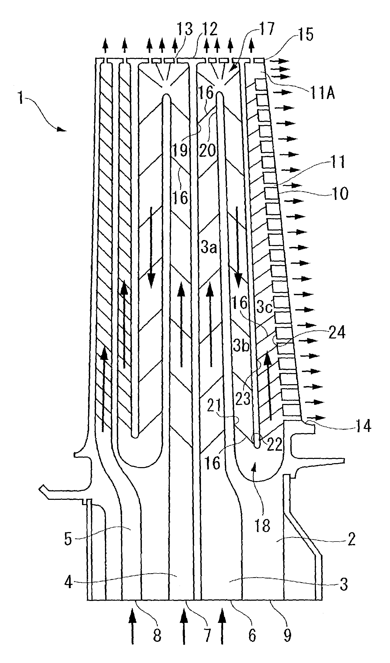
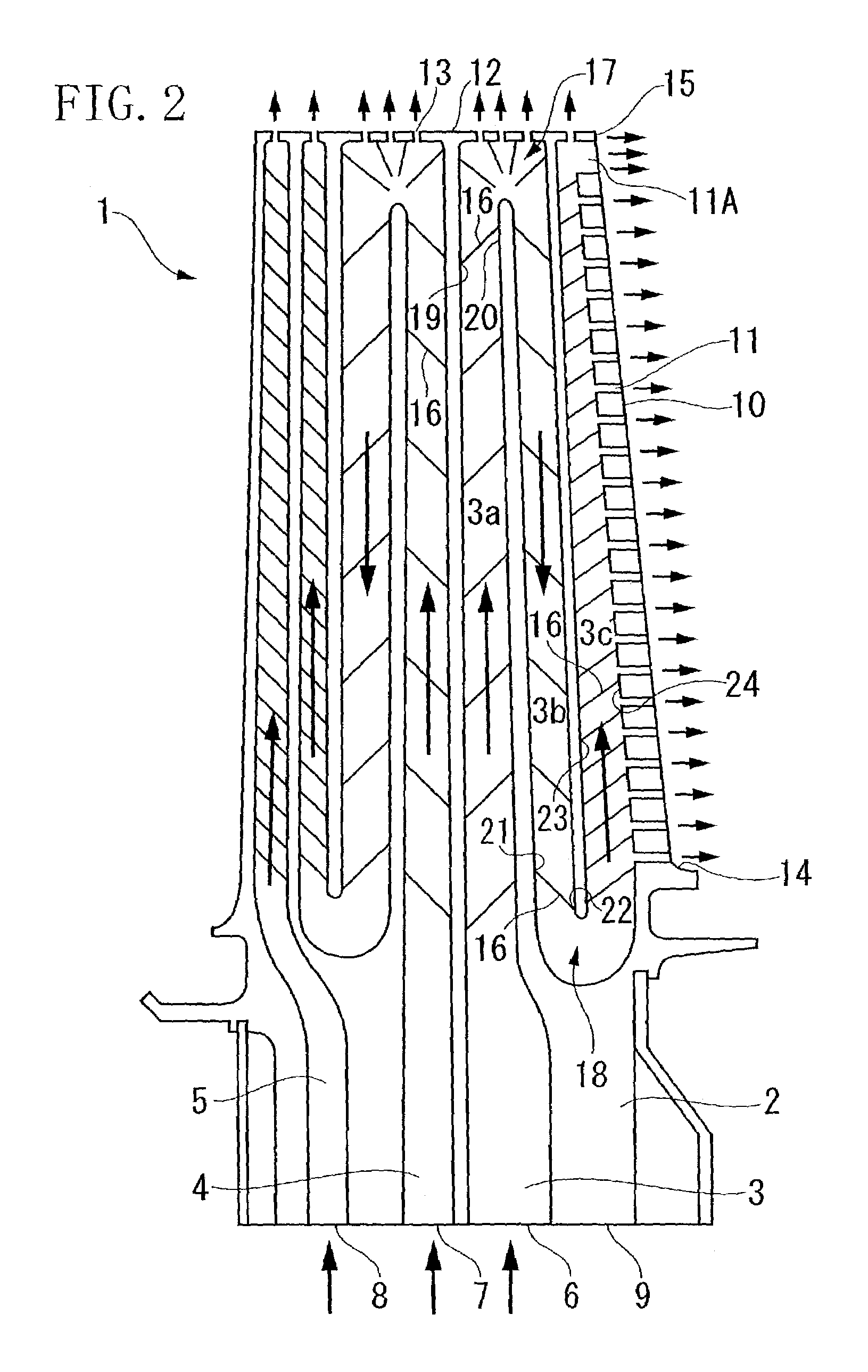
[0030]An internal cross-sectional view of the turbine moving blade 1 used in the gas turbine 40 is shown in FIG. 2. The base 2 of the turbine moving blade 1 is fixed to the rotating shaft 47, internal flow paths 3, 4 and 5 are provided therein, and supply openings 6, 7, and 8 that supply cooling medium are provided in a base surface 9...


PUM


Abstract

The object of the present invention is to provide a turbine moving blade that has high heat resistance and can be used for a long period of time by improving the cooling efficiency of the turbine moving blade, and to improve both the thermal efficiency and operating efficiency of a gas turbine through the use of this turbine moving blade. In order to achieve the object, the present invention provide a turbine moving blade arranged in a combustion gas flow path in which a plurality of blow-out openings for blowing out a cooling medium are formed in its outer surface, wherein among a plurality of cooling medium trailing edge blow-out openings arranged from the vicinity of a blade base to the vicinity of a blade tip along a blade trailing edge of turbine moving blade, the opening area of a blade tip trailing edge blow-out opening located in the vicinity of blade tip is set to be larger than the opening area of the other trailing edge blow-out openings.

Description

BACKGROUND OF THE INVENTION[0001]1. Field of the Invention[0002]The present invention relates to a turbine moving blade of a gas turbine suitably used in a power generation plant and so forth as well as a gas turbine comprising the moving blade, and more particularly, to a turbine moving blade provided with a cooling structure.[0003]2. Description of the Related Art[0004]It is effective to increase the temperature of the combustion gas (fluid) for operation at the turbine inlet in order to improve the thermal efficiency of industrial gas turbines used in power generation plants and so forth. On the other hand, since the heat resistance performance of the turbine moving blades, stationary blades and other members exposed to combustion gas is restricted by the physical properties of their materials, it is not possible to simply raise the turbine inlet temperature.[0005]Therefore, thermal efficiency is increased by ensuring the heat resistance performance of the turbine blades by incre...

Claims


Application Information

Patent Timeline
Patent Type & Authority Patents(United States)
IPC IPC(8): B63H1/14F01D5/18F02C7/18
CPCF01D5/186F01D5/187F05D2260/22141Y02T50/676Y02T50/60
Inventor SOECHTING, FRIEDRICHELLIS, CHARLESTOMITA, YASUOKITORII, SHUNSUKE
Owner MITSUBISHI HITACHIPOWER SYST LTD
Why Eureka
Try Eureka