
Signal receiver using coherent integration in interleaved time periods for signal acquisition at low signal strength

a signal receiver and interleaved time period technology, applied in the field of global positioning system (gps) receivers, can solve the problems of nullifying the processing gain of integration times beyond 20 ms, limited application of global positioning system, and difficult indoor use of gps, so as to improve the probability of rapid acquisition of weak signals, increase the tolerance for time errors, and increase the signal processing gain

Active Publication Date: 2006-01-24
TRIMBLE NAVIGATION LTD
View PDF4 Cites 13 Cited by
  • Summary
  • Abstract
  • Description
  • Claims
  • Application Information

AI Technical Summary

Benefits of technology

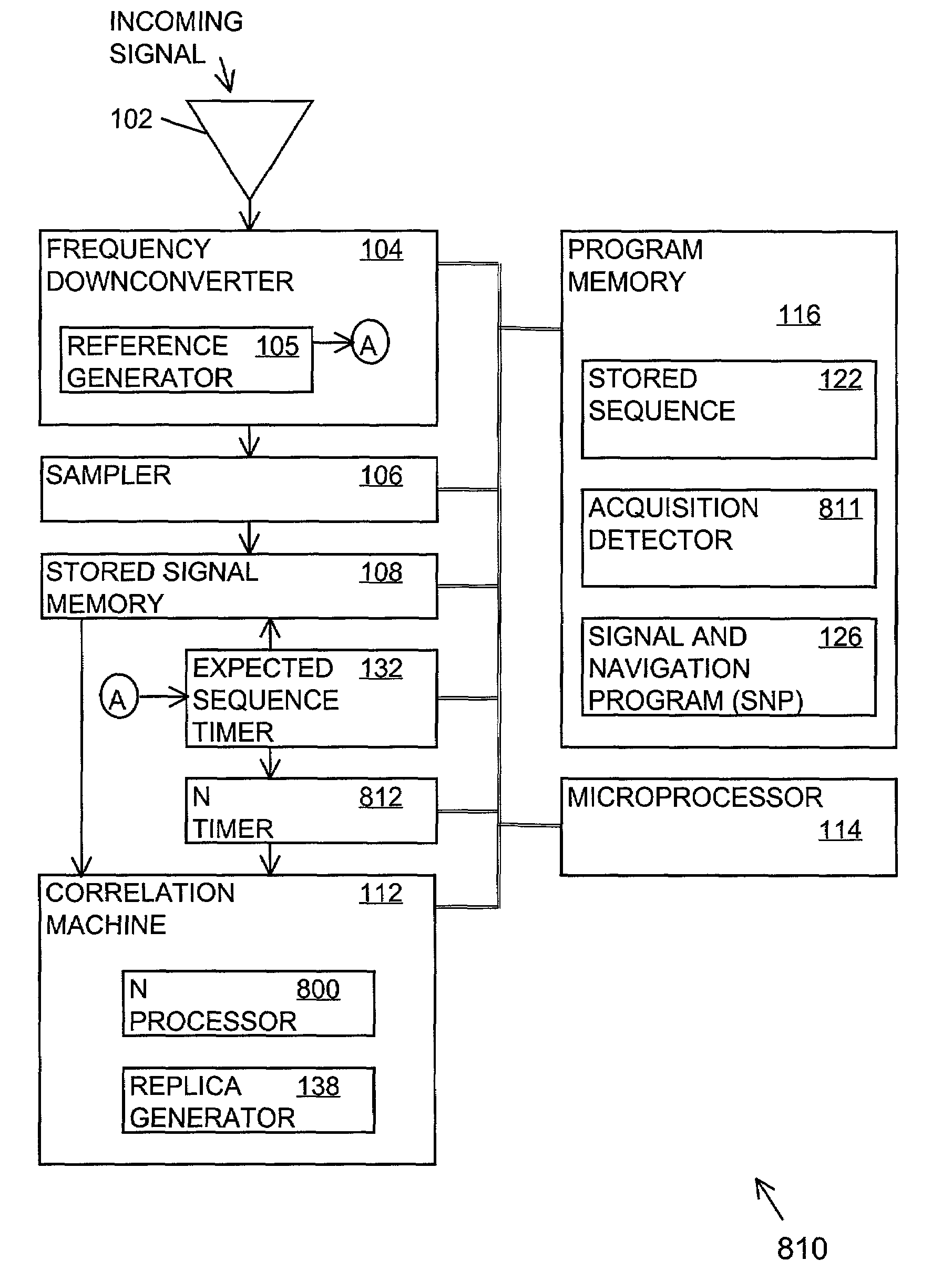
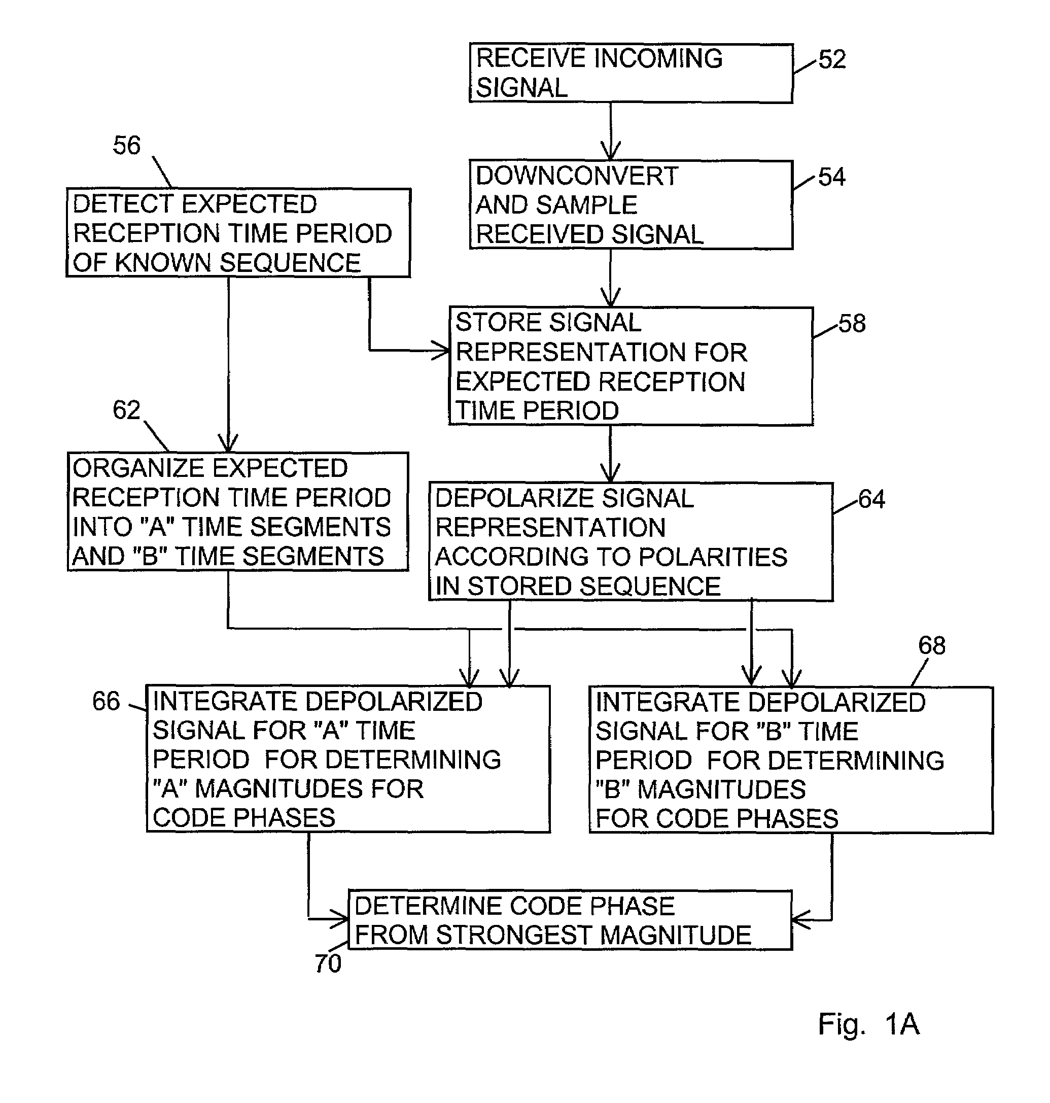
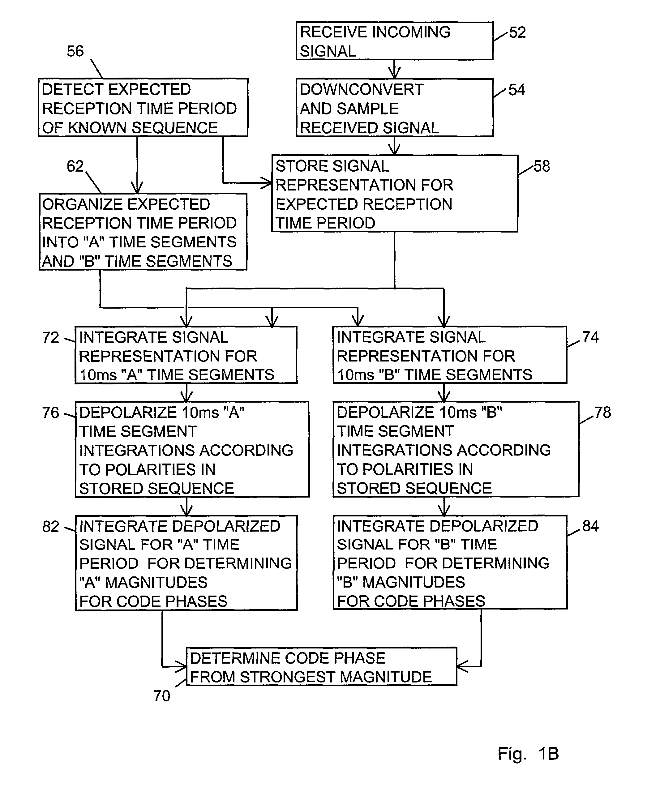
[0010]Briefly, an object of the present invention is to acquire a signal having data bits spread by a spreading code even when the spread spectrum signal is weak by integrating the signal in separate interleaved time periods termed “A” and “B” time periods where the “A” time period includes “A” time segments and the “B” time period includes “B” time segments that alternate with the “A” time segments. Known polarities of expected data bits having a known expected reception time period are used to invert or not invert (depolarize) the signal separately for each time segment. By constructing the time segments to be one-half a data bit period, at least one of the “A” and “B” time segments avoids transitions in the GPS data bits, thereby enabling a continuous integration without the nullifying effect of inversions of the data bits. A preferred embodiment of the present invention is described in terms of a spread spectrum global positioning system (GPS) signal. In order to more easily follow the summaries of embodiments, the reader may first want to refer to FIGS. 6A–E.
[0014]Each of the 10 ms “A” and “B” time segments includes 10 epochs for the 1 ms GPS spreading code. An advantage of the present invention is that a large signal processing gain is achieved due to the length of time of the “A” time period (or the “B” time period), thereby improving the probability of rapid acquisition of a weak signal.

Problems solved by technology

However, the global positioning system has been limited in several potential applications because existing GPS receivers are unable to acquire a GPS signal unless the GPS signal has a relatively clear line of sight to the GPS satellites ensuring strong GPS signals.
However, the signal strength requirements of GPS receivers make it difficult to use GPS indoors or where the GPS signal may be weak due to the attenuation of passing through buildings or trees.
Unfortunately, every 20 ms the C / A PRN code may be inverted with a new GPS data bit, thereby nullifying the processing gain for integration times beyond 20 ms.

Method used


Image

  • Signal receiver using coherent integration in interleaved time periods for signal acquisition at low signal strength
  • Signal receiver using coherent integration in interleaved time periods for signal acquisition at low signal strength
  • Signal receiver using coherent integration in interleaved time periods for signal acquisition at low signal strength

Examples


first embodiment

[0081]In a first embodiment shown in FIG. 7A, a block 702 depolarizes a representation of the incoming signal for the known polarities of the expected GPS data bits for providing a depolarized signal. A block 704 integrates the depolarized signal for time lengths not greater than the time segments for providing depolarized integrations. A block 706 separates the “A” time segments and the “B” time segments for the depolarized integrated signal for providing “A” and “B” depolarized integrations, respectively. Then, a block 708 further integrates (accumulates) the “A” depolarized integrations over the entire “A” time period for providing the “A” time period magnitudes and further integrates (accumulates) the “B” depolarized integrations over the entire “B” time period for providing the “B” time period magnitudes.

second embodiment

[0082]In a second embodiment shown in FIG. 7B, a block 710 depolarizes a representation of the incoming signal for the known polarities of the expected GPS data bits for providing a depolarized signal. A block 712 separates the “A” time segments and the “B” time segments for the depolarized signal for providing an “A” depolarized signal and a “B” depolarized signal, respectively. Then, a block 714 integrates the “A” depolarized signal over entire “A” time period for providing the “A” time period magnitudes and integrates the “B” depolarized signal over the entire “B” time period for providing the “B” time period magnitudes.

third embodiment

[0083]In a third embodiment shown in FIG. 7C, a block 720 integrates a representation of the incoming signal for time lengths not greater than the time segments for providing first integrations of the signal. A block 722 depolarizes the first integrations for the known polarities of the expected GPS data bits for providing depolarized integrations. A block 724 separates the depolarized integrations according to the “A” and “B” time segments for providing “A” and “B” depolarized integrations, respectively. Then, a block 726 further integrates the “A” depolarized integrations over the entire “A” time period for providing the “A” time period magnitudes and further integrates the “B” depolarized integrations over the entire “B” time period for providing the “B” time period magnitudes.


PUM


Abstract

A GPS receiver and method using alternating “A” and “B” integration time segments. The polarities of certain GPS data bits are known beforehand and their expected reception times are known. The GPS signal in 10 millisecond “A” time segments and “B” time segments is depolarized according to the known polarities. The depolarized GPS signal during an “A” time period made up of all the “A” time segments is integrated for providing an “A” time period magnitude for each code phase. Likewise, the depolarized GPS signal during a “B” time period made up of all the “B” time segments is integrated for providing a “B” time period magnitude for each potential GPS code phase. The strongest of the time period magnitudes is compared to a correlation threshold for selecting a code phase for signal acquisition.

Description

BACKGROUND OF THE INVENTION[0001]1. Field of the Invention[0002]The invention relates generally to a global positioning system (GPS) receiver and more particularly for a GPS receiver integrating a GPS signal for an “A” time period having “A” time segments and integrating the GPS signal for a “B” time period having “B” time segments, where the “A” time segments and the “B” time segments alternate, for signal acquisition at a low signal strength.[0003]2. Description of the Prior Art[0004]The global positioning system (GPS) is a system using GPS satellites for broadcasting GPS signals having information for determining location and time. Each GPS satellite broadcasts a GPS signal having 20 milliseconds (ms) GPS data bits modulated by a 1 ms pseudorandom noise (PRN) code having 1023 bits or chips. The PRN code for each GPS satellite is distinct, thereby enabling a GPS receiver to distinguish the GPS signal from one GPS satellite from the GPS signal from another GPS satellite. The 20 ms ...

Claims


Application Information

Patent Timeline
Patent Type & Authority Patents(United States)
IPC IPC(8): H04B1/69H04B1/707G01S19/30G01S1/00G01S19/24H04B1/7077
CPCG01S19/24H04B1/70775G01S19/30H04B2201/70715
Inventor LOOMIS, PETER VAN WYCKYU, YIMING
Owner TRIMBLE NAVIGATION LTD
Learn More