
Wireless, ground link-based aircraft data communication method

a data communication and ground link technology, applied in the field of communication systems, can solve the problems of complex and expensive components, high cost, and high time and manpower consumption, and achieve the effect of increasing the transmit power level and reliable reception

Inactive Publication Date: 2006-01-24
HARRIS CORP
View PDF17 Cites 67 Cited by
  • Summary
  • Abstract
  • Description
  • Claims
  • Application Information

AI Technical Summary

Benefits of technology

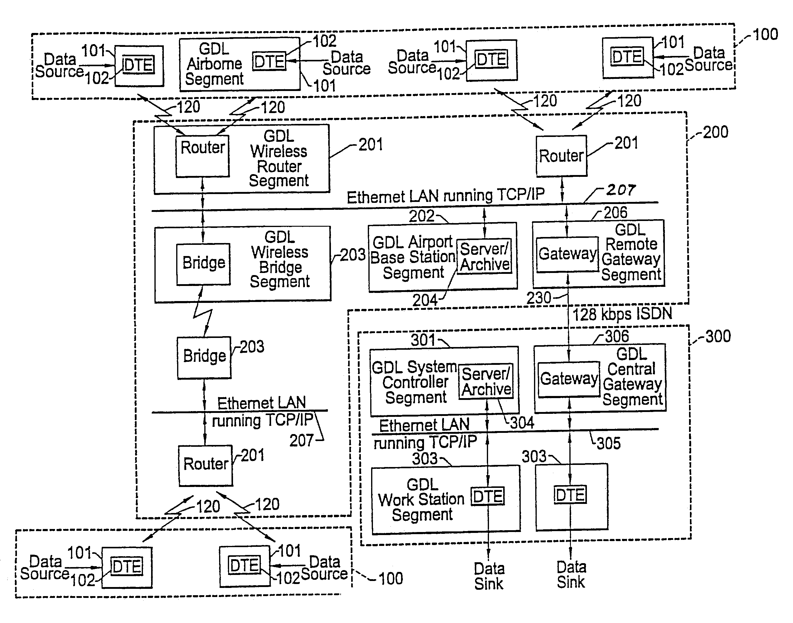
[0010]In accordance with a preferred embodiment of the invention, this wireless ground data link is implemented as a spread spectrum RF link, preferably having a carrier frequency lying in a reasonably wide (on the order of 100 MHz) unlicensed 2.4–2.5 GHz S-band segment, which provides the advantage of global acceptance. A benefit of spread spectrum modulation is its inherently low energy density waveform properties, which are the basis for its acceptance for unlicensed product certification. Spread spectrum also provides the additional benefits of resistance to jamming and immunity to multipath interference.
[0017]In a preferred embodiment, a respective wireless router employs a source coding system that achieves bandwidth reduction necessary to permit either multiple audio channels to be multiplexed onto the wireless transmit carrier to the GDL unit, video to be transmitted over a ground subsystem's wireless router-to-GDL unit ground link frequency channel, or data files to be compressed to maximize system throughput and capacity during communications (uploads to or downloads from) the aircraft.
[0020]The wireless router transceiver includes a control processor which ensures robust system performance in the dynamically changing unlicensed spread spectrum interference environment of the ground data link by making decisions based on link signal quality, for the purpose of setting transmit power level, channel frequency assignment, and antenna selection. The ground subsystem processor also initiates a retransmission request to an aircraft's GDL unit upon detection of a bit error in a downlinked flight performance data packet.
[0023]The spread spectrum transceiver in each of an aircraft's GDL unit and an associated airport wireless router includes a frequency agile spread spectrum transmitter, a frequency agile spread spectrum receiver and a frequency synthesizer. In addition to being coupled to an associated control processor, the spread spectrum transmitter is coupled to an adaptive power control unit and an antenna diversity unit. Such a power allocation mechanism makes more efficient use of available power sources, reduces interference, and makes more efficient use of the allocated frequency spectrum. The control processors at each end of the wireless ground link execute a communication start-up protocol, through which they sequentially evaluate all of the available frequency channels in the unlicensed 2.4–2.5 GHz S-band segment of interest and assess the link quality of each of these channels.
[0025]As described earlier, in an environment such as a large commercial airport, a common cause of reduced signal quality is multipath interference resulting from sudden attenuation in the direct path between the transmitters and the receivers in the wireless router and aircraft, in conjunction with a delayed signal arriving at the receiver from a reflected path. This sudden attenuation in the direct path between the aircraft and the wireless router can result in the destructive summation of multiple paths at the antenna in use, resulting in a severe signal fading condition. The nature of multipath is such that switching to a second spatially separated or orthogonally polarized antenna can result in a significant improvement in link performance. Since the wireless networking environment of an airport is one in which objects are likely to be moving between the wireless router and the aircraft, and one of the platforms (the aircraft) is mobile, antenna diversity can make the difference between reliable and unreliable system performance.

Problems solved by technology

Although installing such a redundant flight data recording unit allows airline personnel to retrieve a copy of the flight performance data for subsequent evaluation, when considering the large volume of aircraft traffic experienced by major commercial airports, the above-proposed scheme is not only extremely time and manpower intensive, but is prone to substantial misidentification and aircraft / data association errors.
Obvious drawbacks to these systems are the fact that not only do they employ complex and expensive components, but require that the aircraft be parked at the gate, so that the line-of-sight infrared transceivers or the fiber optic connection assemblies can be properly interlinked.
As a consequence, neither of these types of systems is effective for use with commuter, cargo or military aircraft, which are customarily parked on an apron, rather than at a mating jetway, where such an optical link is to be provided.

Method used


Image

  • Wireless, ground link-based aircraft data communication method
  • Wireless, ground link-based aircraft data communication method
  • Wireless, ground link-based aircraft data communication method

Examples


Embodiment Construction

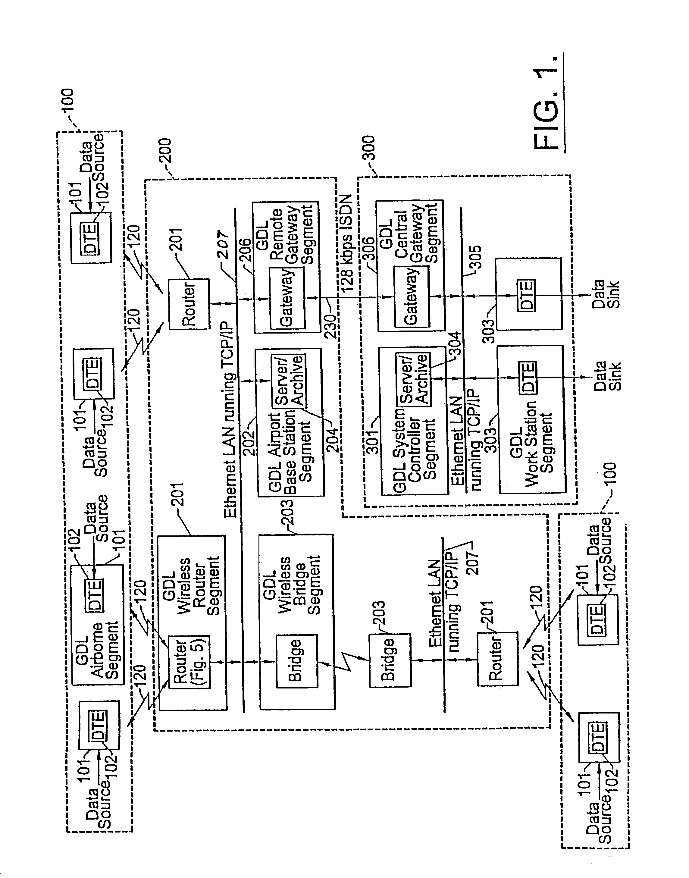
[0039]Before describing in detail the wireless ground link-based aircraft data communication system in accordance with the present invention, it should be observed that the present invention resides primarily in what is effectively a prescribed arrangement of conventional avionics and communication circuits and associated digital signal processing components and attendant supervisory control circuitry therefor, that controls the operations of such circuits and components. Consequently, the configuration of such circuits and components and the manner in which they are interfaced with other communication system equipment have, for the most part, been illustrated in the drawings by readily understandable block diagrams, which show only those specific details that are pertinent to the present invention, so as not to obscure the disclosure with details which will be readily apparent to those skilled in the art having the benefit of the description herein. Thus, the block diagram illustra...


PUM


Abstract

A flight information communication system has a plurality of RF direct sequence spread spectrum ground data links that link respective aircraft-resident subsystems, in each of which a copy of its flight performance data is stored, with airport-located subsystems. The airport-located subsystems are coupled by way communication paths, such as land line telephone links, to a remote flight operations control center. At the flight operations control center, flight performance data downlinked from plural aircraft parked at different airports is analyzed. In addition, the flight control center may be employed to direct the uploading of in-flight data files, such as audio, video and navigation files from the airport-located subsystems to the aircraft.

Description

[0001]This application is a continuation of Ser. No. 09 / 976,647, filed Oct. 11, 2001, which is a continuation of Ser. No. 09 / 714,584 filed on Nov. 16, 2000, now issued U.S. Pat. No. 6,308,045, which is a continuation of Ser. No. 09 / 474,894, filed Jun. 2, 1999, now issued U.S. Pat. No. 6,154,637, which is a continuation of Ser. No. 08 / 557,269, filed Nov. 14, 1995, now issued U.S. Pat. No. 6,047,165, the disclosures of which are hereby incorporated by reference in their entirety.FIELD OF THE INVENTION[0002]The present invention relates in general to communication systems, and is particularly directed to an aircraft data communication system having a plurality of wireless ground links that link respective aircraft-resident subsystems, in each of which a copy of its flight performance data is stored, with airport-located ground subsystems, each ground subsystem being coupled, in turn, by way of respective telco links to a remote flight operations control center, where flight performance...

Claims


Application Information

Patent Timeline
IPC IPC(8): H04B7/00G08B21/00G05D1/00G06F17/40G08G5/00
CPCG05D1/0055G08G5/0013G08G5/0021G08G5/0026G08G5/065H04B7/18506
Inventor WRIGHT, THOMAS H.ZIARNO, JAMES J.
Owner HARRIS CORP
Learn More